hi acca sorry for disturbing , but please do a pcb using the 14pin ir2110 .
I tried making one with IR2110, not sure if it's good but here it is...

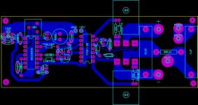
See picture for corrections:
Thanks for the corrections, how's this?

View attachment bottom.pdf
View attachment top.pdf
I haven tested it yet, I was about to etch one but Acca posted some corrections so I'm redwaring it and waiting for feedback.stewin; said:thanks 0t0 , nice one .have you tested it? please post pcb files.
Not good.This two lines must go to source pin of fet,same as on my picture.
what is the advantage of using dual lines as you have drawn ?
Not good.This two lines must go to source pin of fet,same as on my picture.
Ok, I fixed it

View attachment top.pdf
View attachment bottom.pdf
This is better.
Thanks a lot for the design corrections.
I have just a couple of questions before I build it, what FETs would you recommend for a Bridge @2ohms with a supply +/-40 (max +/-50V unloaded)
Would something like IRFP250N work good?
thanks in advance.
Fet with smallest Qg will be better,but if you don't have any this is ok.
woow that was fast 🙂
I'll look for some other fets and post if I find anything.
I'll be building the amp tomorrow.
Yes,and fets will be fast too 😉
I'll wait for pics 😉
Use series limiting bulb with power transformer.
I'll wait for pics 😉
Use series limiting bulb with power transformer.
Yes,and fets will be fast too 😉
I'll wait for pics 😉
Use series limiting bulb with power transformer.
I'll probably order some IRFB4227 fets later, for now I'll do my testing with IRFP250N.
Pics to come tomorrow 🙂
Also I intend to power this (after testing with regular transformer of course) from a car SMPS.
Have you measured the efficiency of the amplifier?
p.s. sadly the store I order my components from is doing some kind of maintenance to their warehouse and I won't be able to order some of the component for another week 🙁.
Effidency is better than some class D amp's on this forum,because PWM goes from 0 to ~98%
It's better than self osc. amps.
It's better than self osc. amps.
Hi Aleks,what will be the highest or maximum output(watt's) by using -/+ 90V approximately?I'll already try it on -/+56V it has a lot of power,just one more question it doesn't have a feedback will it run safely at full power,thank's.
Max output:
P=U^2/R
With +/-90V,RMS voltage will be 64V (idealy)
On real amp,this will cca. 60V (with 90V stable).
60*60=3600
3600/4ohm=900W
3600/8ohm=450W
Feedback isn't problem.
Just set potentiometer to 0V at output (50% duty cycle).Glue pot if wish,to prevent move from vibrations.0V at output will be very stable.
First try with lower voltages.
Thank you so much Aleks,hope i can find a solution to the noisy output came from my speaker's,it's around 60 hertz something maybe from my power supply cause i'm using a linear one,hope to hear more from you.
- Status
- Not open for further replies.
- Home
- Amplifiers
- Class D
- DIY Good Class D amplifier