@peppennino
I got a PSU pcb gerber from Ben Mah.
https://www.diyaudio.com/community/threads/diy-front-end-2022.394339/post-7313031
I got a PSU pcb gerber from Ben Mah.
https://www.diyaudio.com/community/threads/diy-front-end-2022.394339/post-7313031

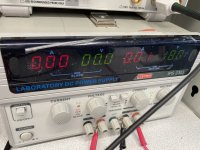
I'm getting a huge DC voltage at R5 (16.83V), where it has been advised to measure DC offset. Is this normal?
I am using the meanwell 36V power supply used for the Sony VFET amp, as I wanted to test this for using as a front end in that amp. It is running through Mark Johnson's TUBA filter. The voltage out of that filter comes out to 33.95V. So, PSU is single ended and input signal is also single ended.
I have R7 = 332, R6 = 750R, R1 & R2 = 10K
It plays fine if I let the DC voltage bleed off before turning on my amp.
I have taken the following measurements:
Comp Value Voltage Voltage across R
R5 100R 16.83V 0
R6 750R 32.53 .742
R7 332R 1.335 1.334
R8 100R .859 .857
R9 46.7R 33.28 .671
R13 10R 33.16 .115
Attachments
If you are powering it with 33.95V, then 16.83V is normal. In order for the voltage to be at or near zero, a bipolar power supply is needed.
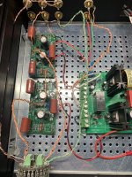
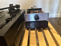
Finally got around to finishing my FE 2022.
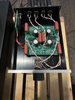
I went with matched 2SK170s from punkydawgs. Panasonic 3.3uf polypropylene caps with WIMA 0.1uf FKP under the PCB. Had an Audio Note 100K volume pot in my stash so I used that. Using a Mean Well 48VDC SMPS with the DIYAudio Store SMPS filter. Bought a matching case to my Darlington Labs MP8B phono preamp to package everything in.
Powered it up and it’s already making really good music. Will take a while powered up for the caps to settle in until I can fully evaluate. But it’s sounding pretty damn nice from the start. But there is a slight increase in the noise floor compared to the el cheapo Nitsch Piety I was using to control volume before. Probably replacing the 100K pot with a 10K one will cure that.
Still to do:
DIY is fun!
I went with matched 2SK170s from punkydawgs. Panasonic 3.3uf polypropylene caps with WIMA 0.1uf FKP under the PCB. Had an Audio Note 100K volume pot in my stash so I used that. Using a Mean Well 48VDC SMPS with the DIYAudio Store SMPS filter. Bought a matching case to my Darlington Labs MP8B phono preamp to package everything in.
Powered it up and it’s already making really good music. Will take a while powered up for the caps to settle in until I can fully evaluate. But it’s sounding pretty damn nice from the start. But there is a slight increase in the noise floor compared to the el cheapo Nitsch Piety I was using to control volume before. Probably replacing the 100K pot with a 10K one will cure that.
Still to do:
- Add 3mm blue power-on LED
- Counterbore front panel then anodize black to match my Darlington Labs MP8B
- Replace AN 100K pot with TKD 2CP-2511 10K unit.
- Experiment tapping into my amp’s B+ for 44VDC to replace 48VDC SMPS
DIY is fun!
Attachments

I have found that this pre sounds the best with a +/-24VDC regulated linear PSU, and also with parallel Toshiba 2SK170BL matched Jfets. In this mode, it is hard to beat as a great line level pre amp - the best I have built so far - your last sentence sums it up well.
Yes. It even works well as an actual power amplifier front end, too.
Last edited:
@Ben Mah regarding post Previous Post/Answer
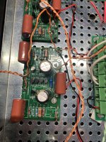
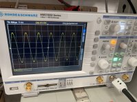
... At some point, pressed by time & no cellphone signal @local fab lab [underground], i couldn't verify the correct wiring and...well did it my initial way, quickly check the signal and got a truncated sinus (quick drawing).

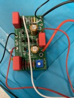
So yeah, prepared better, soldered the way you recommended, tested, everything is fine. Pictures attached just for reference and the fun of sharing experience.Thanks again for your initial advice!
... At some point, pressed by time & no cellphone signal @local fab lab [underground], i couldn't verify the correct wiring and...well did it my initial way, quickly check the signal and got a truncated sinus (quick drawing).
So yeah, prepared better, soldered the way you recommended, tested, everything is fine. Pictures attached just for reference and the fun of sharing experience.Thanks again for your initial advice!
Attachments
Hi guys, is this kit still available on the Diyaudiostore? It seems I can't can't find it anymore over there.
Many thanks!
Gaetano.
Many thanks!
Gaetano.
Hi Gaetano -
Was this what you were looking for?
https://diyaudiostore.com/products/diy-front-end-2022?_pos=1&_sid=b0839787e&_ss=r
Was this what you were looking for?
https://diyaudiostore.com/products/diy-front-end-2022?_pos=1&_sid=b0839787e&_ss=r
A question for builders out there.
Really enjoying my DIY FE 2022 being used as a line amp. I’m using a Mean Well 48VDC SMPS to power it with the DIYaudio Store P089ZB DC Filter. Using quad matched 2SK170s too, as they should be quieter.
In my system with 88dB/watt speakers, there is a very slight whirring sound heard at normal listening levels (9 o’clock volume position). Cranking full level level, increases the noise level, with a different character. This did not happen with the el cheapo Nitsch Piety I was using in that position earlier. That was dead silent.
Any opinions if a Linear power supply would help quiet the thing? How about installing C6 compensation caps? I don’t have a scope to investigate if it’s oscillating. Just looking for some direction here in my next step to debug.
Other than that, it’s doing a wonderful job in my system. Many thanks to Nelson for such a generous gift to us all!
I suggest powering with the SMPS only (no filter) to hear if that is silent. SMPS can be silent too.
Pictures of your build may or may not be revealing, but post some as it may help in the trouble shooting.
Pictures of your build may or may not be revealing, but post some as it may help in the trouble shooting.
Reposting pic.I suggest powering with the SMPS only (no filter) to hear if that is silent. SMPS can be silent too.
Pictures of your build may or may not be revealing, but post some as it may help in the trouble shooting.
Will try the SMPS directly.
Also try Mark’s licky finger probe.
Thanks!
Attachments
G'day Guys,
I am preparing to build a preamp using the FE2022.
First things first is to get my head around the schematic. I think I have understood the documentation.

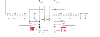
I think I have recreated the schematic here as I think one would implement a single ended preamp stage set for 2x gain.
I have used the improvements from the V0R1 schematic and removed the auxiliary components not needed:
-Removed C2 and R2 as it will be single ended.
-Removed the pot for DC offset reduction, I will use a bipolar power supply.
-Removed R14, not needed for a preamp.
-Removed C6, not needed for a preamp.
Am I correct here?
Did I pass the test?
I am preparing to build a preamp using the FE2022.
First things first is to get my head around the schematic. I think I have understood the documentation.
I think I have recreated the schematic here as I think one would implement a single ended preamp stage set for 2x gain.
I have used the improvements from the V0R1 schematic and removed the auxiliary components not needed:
-Removed C2 and R2 as it will be single ended.
-Removed the pot for DC offset reduction, I will use a bipolar power supply.
-Removed R14, not needed for a preamp.
-Removed C6, not needed for a preamp.
Am I correct here?
Did I pass the test?
You still need the shunt element on the feedback leg (C2, R2). C2 will go to ground for a single ended setup. I would go R1=R2=10k, R3=R4=20k, C2=3.3uF. The R2 in your picture should be renamed R3 to avoid confusion, so the designator matches NP's original article.
Thank you.You still need the shunt element on the feedback leg (C2, R2). C2 will go to ground for a single ended setup. I would go R1=R2=10k, R3=R4=20k, C2=3.3uF. The R2 in your picture should be renamed R3 to avoid confusion, so the designator matches NP's original article.
It looks like I failed the test....
I triple checked my designations and r2 still got passed me somehow...
I'll have another go tomorrow night.
Right, 2nd attempt.

Drawn this way the feedback loop is more obvious to me now.
Looking at the value of C2 and looking at the frequency response in the PDF from Papa.
There appears to be some rolloff below 60Hz

Would increasing the value of C2 to something like 22uF remove this rolloff?
I can't quite figure out what kind of pass filter is employed here in the feedback path or exactly what elements constitute the filter?
Is this a 2nd order CR filter:

Where R1 = R4R, C1 = 0, R2 = R2R and C2 = C2R
Drawn this way the feedback loop is more obvious to me now.
Looking at the value of C2 and looking at the frequency response in the PDF from Papa.
There appears to be some rolloff below 60Hz
Would increasing the value of C2 to something like 22uF remove this rolloff?
I can't quite figure out what kind of pass filter is employed here in the feedback path or exactly what elements constitute the filter?
Is this a 2nd order CR filter:
Where R1 = R4R, C1 = 0, R2 = R2R and C2 = C2R
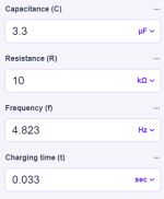
It's a good ol' RC time constant, capacitor charge time stuff ("t"). I jammed some numbers into the calculator at omnicalculator for my little example.. Shooting for something under 5Hz seems reasonable. I've seen some designers use values that put the number way under that, and of course you see it higher too. Nothing is set in stone. You can use a big fat (big value) electrolytic there to keep the AC voltage across it low (and hence any "cap distortion" low) if you want, that certainly works too.
Attachments
Last edited:
- Home
- Amplifiers
- Pass Labs
- DIY Front End 2022