
Technical question.. why does Pa use a zener reference for the current source arrangement on some of his circuits? (re-done Stasis FE for example) I thought zeners were kinda noisy. Seems like a two-transistor feedback circuit would have better performance while still being simple / have low parts count.
be sure that, whatever Pa is using, it's good enough
can it be better ..... or "better", yes
will it sound better ..... well, feel free to experiment, and establish your own habits
can it be better ..... or "better", yes
will it sound better ..... well, feel free to experiment, and establish your own habits
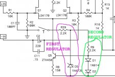
One technical answer is: the current source bias voltage (at the base of Q5) is regulated twice. R29 + D5 create a regulated voltage which is 9.1 volts above the bottom rail. This once-regulated voltage is then fed into a second voltage regulator, R9 + D1-D2, creating a very stable, twice-regulated, bias voltage at the base of Q5.
Thanks to cascaded regulators, the bias voltage is extremely insensitive to supply voltage ripple / hum, and extremely insensitive to amplifier output current induced supply bounces.
I liked the idea so well I used it myself, in the "Mountain View" input card (March 2018) and also in the "Bulwark" input card (June 2021), both of which are in the diyAudio Store.
Oh and John Curl / Richard Burwen / Madrigal technicians used the same Zener circuit for double regulated bias sources in the Mark Levinson ML-2 class A power amp (1981).
_
Attachments
Last edited:
HOW CONSTANT IS THE "CONSTANT CURRENT SOURCE" ON THE OUTPUT? WHAT IS ITS OUTPUT IMPEDANCE?
After studying the circuit schematic (Figure 0 attached), I asked myself the question above, and spent an hour in the lab yesterday afternoon taking measurements to find some answers. Executive summary: it's pretty darn constant. Output impedance is above 100 kOhms.
I built the CCS circuit and attached it to a curve tracer, then swapped in a total of 42 different J113 JFETs from my parts drawer. Why 42? Because, spending an hour on the project, creating the fixture, running the curves, and capturing the plots . . . . that's how many I was able to test before the hour was up. In the plots below, the set of 42 different J113 devices are given the grandiose name "population My42". Mostly that's to remind people who look at the plots but don't read this explanation, it isn't a huge experiment involving every J113 ever produced in the history of the world. It's just a couple handfuls of parts that one guy measured, in one hour, before dinnertime.
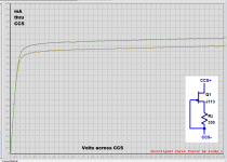
After testing all 42 JFETs, I chose one that I felt was representative or "typical" of this population. JFETs are notorious for having a lot of unit-to-unit variation, and my sample of 42 units certainly had tons of variation too. The "typical" unit was representative of the most commonly seen CCS performance; statisticians call this the "mode" of the distribution. When connected as a DIY Front End constant current source, the "typical" units measured performance was captured, it's in Figure 1 attached.
When we magnify the flat part of Figure 1 where the current is approximately constant, we get Figure 2 attached. This makes it easier to read the output currents with greater precision. Then when a tangent line is overlaid (Figure 3), we can extract the constant current source's output impedance: Zout = deltaV / deltaI , and that's about 110 kOhms or so, assuming the Front End runs from high supply voltages as Nelson Pass intended. Very nice.
I asked myself the question: if I arbitrarily discarded two thirds of the population, and only kept those J113's which gave the tightest matching of constant current behavior, just how tight would that be? What's the benefit of measuring and then throwing away 2/3rds of the parts? Figure 4 provides an answer, for this small population of 42 JFETs. The tightest matching among current sources, gives output currents which vary between 7mA and 8mA. Call it 7.5mA plus or minus 0.5mA ... or equivalently, 7.5mA plus or minus 7 percent.
The worst "outlier" J113 constant current sources (among the ones that I discarded to get Figure 4), are plotted in Figure 5 and Figure 6. We see that this small population of 42 JFETs included one that gave 8.8 mA of output current, and also included another that gave 4.0 mA of output current. So maybe, just maybe, discarding some portion of the population is a beneficial (if costly) idea.
When does the constant current source poop out, and cease to be a CCS? One possible answer is shown in Figure 7. As you decrease the voltage across the CCS circuit, its output current falls. And if you decrease the voltage across the CCS to just 700 millivolts, the output current falls by 50 percent. I would say the CCS has pooped out by then.
Figure 8 is a plot of the "typical" J113 but all by itself, as a 3 terminal amplifying device rather than as a 2 terminal current source. VGS is on the horizontal axis and IDS is on the vertical axis. I provide this to assist people that studied semiconductor physics at university, and who wish to extract the modeling coefficients of this "typical" device from the My42 population, using the square-law JFET model found in textbooks and included in circuit simulators. When you extract a J113 model, compare its simulated behavior against the measured behavior shown in Figure 8 and in Figure 1.
Finally, Figure 9 is just Figure 8 with two datapoints highlighted, labeled A and B. Readers can ponder the significance of A and B, and post their explanations here for the benefit of others. I'll post my own in ten days (Jan 27), to avoid stepping on the toes of members who only read diyAudio once a week.
_
After studying the circuit schematic (Figure 0 attached), I asked myself the question above, and spent an hour in the lab yesterday afternoon taking measurements to find some answers. Executive summary: it's pretty darn constant. Output impedance is above 100 kOhms.
I built the CCS circuit and attached it to a curve tracer, then swapped in a total of 42 different J113 JFETs from my parts drawer. Why 42? Because, spending an hour on the project, creating the fixture, running the curves, and capturing the plots . . . . that's how many I was able to test before the hour was up. In the plots below, the set of 42 different J113 devices are given the grandiose name "population My42". Mostly that's to remind people who look at the plots but don't read this explanation, it isn't a huge experiment involving every J113 ever produced in the history of the world. It's just a couple handfuls of parts that one guy measured, in one hour, before dinnertime.
After testing all 42 JFETs, I chose one that I felt was representative or "typical" of this population. JFETs are notorious for having a lot of unit-to-unit variation, and my sample of 42 units certainly had tons of variation too. The "typical" unit was representative of the most commonly seen CCS performance; statisticians call this the "mode" of the distribution. When connected as a DIY Front End constant current source, the "typical" units measured performance was captured, it's in Figure 1 attached.
When we magnify the flat part of Figure 1 where the current is approximately constant, we get Figure 2 attached. This makes it easier to read the output currents with greater precision. Then when a tangent line is overlaid (Figure 3), we can extract the constant current source's output impedance: Zout = deltaV / deltaI , and that's about 110 kOhms or so, assuming the Front End runs from high supply voltages as Nelson Pass intended. Very nice.
I asked myself the question: if I arbitrarily discarded two thirds of the population, and only kept those J113's which gave the tightest matching of constant current behavior, just how tight would that be? What's the benefit of measuring and then throwing away 2/3rds of the parts? Figure 4 provides an answer, for this small population of 42 JFETs. The tightest matching among current sources, gives output currents which vary between 7mA and 8mA. Call it 7.5mA plus or minus 0.5mA ... or equivalently, 7.5mA plus or minus 7 percent.
The worst "outlier" J113 constant current sources (among the ones that I discarded to get Figure 4), are plotted in Figure 5 and Figure 6. We see that this small population of 42 JFETs included one that gave 8.8 mA of output current, and also included another that gave 4.0 mA of output current. So maybe, just maybe, discarding some portion of the population is a beneficial (if costly) idea.
When does the constant current source poop out, and cease to be a CCS? One possible answer is shown in Figure 7. As you decrease the voltage across the CCS circuit, its output current falls. And if you decrease the voltage across the CCS to just 700 millivolts, the output current falls by 50 percent. I would say the CCS has pooped out by then.
Figure 8 is a plot of the "typical" J113 but all by itself, as a 3 terminal amplifying device rather than as a 2 terminal current source. VGS is on the horizontal axis and IDS is on the vertical axis. I provide this to assist people that studied semiconductor physics at university, and who wish to extract the modeling coefficients of this "typical" device from the My42 population, using the square-law JFET model found in textbooks and included in circuit simulators. When you extract a J113 model, compare its simulated behavior against the measured behavior shown in Figure 8 and in Figure 1.
Finally, Figure 9 is just Figure 8 with two datapoints highlighted, labeled A and B. Readers can ponder the significance of A and B, and post their explanations here for the benefit of others. I'll post my own in ten days (Jan 27), to avoid stepping on the toes of members who only read diyAudio once a week.
_
Attachments
-
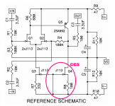 Figure_0.png36.3 KB · Views: 534
 -
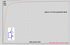 Figure_1.PNG14.5 KB · Views: 523
 -
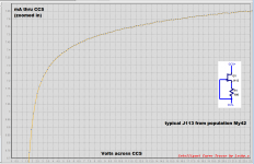 Figure_2.PNG14.6 KB · Views: 349
 -
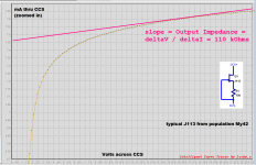 Figure_3.PNG17.5 KB · Views: 366
 -
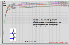 Figure_4.PNG26 KB · Views: 357
 -
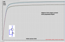 Figure_5.PNG19.2 KB · Views: 353
 -
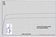 Figure_6.PNG15.8 KB · Views: 347
 -
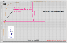 Figure_7.PNG18 KB · Views: 343
 -
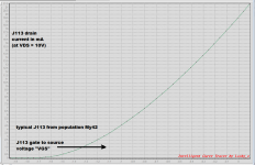 Figure_8.PNG15.8 KB · Views: 342
 -
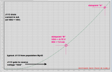 Figure_9.PNG18.2 KB · Views: 527
Thanks to Mark Johnson! Excellent work.
Cheers
Dirk 🙂
p.s.. where have I hidden my J113-group... 🤔
Cheers
Dirk 🙂
p.s.. where have I hidden my J113-group... 🤔
Then when a tangent line is overlaid (Figure 3), we can extract the constant current source's output impedance: Zout = deltaV / deltaI , and that's about 110 kOhms or so, assuming the Front End runs from high supply voltages as Nelson Pass intended. Very nice.
110 kΩ impedance can be expressed as 101 dB isolation from power supply. Q3 CCS will be some 10 dB better. I think that's about maximum one can get from a single JFET CCS.
I just reverified my batch of 2SK369V and Idss is from 16 – 19 mA. As MJ found average J113 Idss to be 19.5 mA, it looks like those that would like to use ‘kosher’ parts can do that. 😀
Nobody knows whether population My42 is, or is not, representative of the tens of millions of J113s manufactured and sold every year.
It's unwise to imagine that an hour's worth of measurements on less than 50 parts, tells you much about the global population. It's also unwise to imagine that the mode of the tiny My42 population, accidentally happens to equal the mean of the global population.
It's unwise to imagine that an hour's worth of measurements on less than 50 parts, tells you much about the global population. It's also unwise to imagine that the mode of the tiny My42 population, accidentally happens to equal the mean of the global population.
Nobody knows whether population My42 is, or is not, representative of the tens of millions of J113s manufactured and sold every year.
It's unwise to imagine that an hour's worth of measurements on less than 50 parts, tells you much about the global population. It's also unwise to imagine that the mode of the tiny My42 population, accidentally happens to equal the mean of the global population.
Many things are not reasonable to assume, but despite that ...
OK, I measured My18 J113 collection at hand. 15 had Idss from 16 – 21 mA. 2 had > 30 mA and 1 had 13.5 mA. Looks like a fair chance.
Should builders rely only on matched and guaranteed JFET from the store or circuit will work well with certain Idss range?
Nobody knows whether population My42 is, or is not, representative of the tens of millions of J113s manufactured and sold every year.
It's unwise to imagine that an hour's worth of measurements on less than 50 parts, tells you much about the global population. It's also unwise to imagine that the mode of the tiny My42 population, accidentally happens to equal the mean of the global population.
Very nice stuff. I'd say that your result have better statistical significance than most trials or polls in their respective field. 😉
voltage across R6 (680R) needs to be one Vbe
so, target current through Q3 needs to be twice that
IR6=0V65/680R=0.96mA
IQ6~2mA
Murphy sez that pretty much every random J113 will have that, combined with 330R in source
besides, what's wrong to have 9V battery at hand, plus DMM, plus 1K trimpot ?
so, target current through Q3 needs to be twice that
IR6=0V65/680R=0.96mA
IQ6~2mA
Murphy sez that pretty much every random J113 will have that, combined with 330R in source
besides, what's wrong to have 9V battery at hand, plus DMM, plus 1K trimpot ?
Could Q3 and Q4 be replaced with resistors, and if so how would the circuits performance change?
Murphy sez that pretty much every random J113 will have that, combined with 330R in source
Where is Murphy wen you need him? 😀
I checked My18 with 332 Ω as a CCS. For 15 average ones, resulting CCS current is from 3.25 – 3.8 mA. Those with >30 mA Idss pushed CCS output to 4 and 5 mA and one with Idss of 13.5 mA dropped current to 2.5 mA.
As for the 2SK369V, Idss may be close but J113 and 2SK369 have different Vgs/Ids curves. Using same 332 Ω, CCS output was from 0.98 – 1.11 mA. They were not intended to be used as CCS anyway, only as a possible Q1/Q2 replacement.
Here are two that don't. They were pretty easy to find, quickly. So they're not rare or exotic.IQ6~2mA
Murphy sez that pretty much every random J113 will have that, combined with 330R in source
_
Attachments
Where is Murphy wen you need him? 😀
I checked My18 with 332 Ω as a CCS. For 15 average ones, resulting CCS current is from 3.25 – 3.8 mA. Those with >30 mA Idss pushed CCS output to 4 and 5 mA and one with Idss of 13.5 mA dropped current to 2.5 mA.
As for the 2SK369V, Idss may be close but J113 and 2SK369 have different Vgs/Ids curves. Using same 332 Ω, CCS output was from 0.98 – 1.11 mA. They were not intended to be used as CCS anyway, only as a possible Q1/Q2 replacement.
I remember that it's worth remembering that Pa used to remember to put Greedy Boyz up to greater tasks
nowadays everyone is expecting no brain involvement, when given with Free Papathing ......... and that being completely his doing

I mean, this as general remark, I know you're remembering Yore

Could Q3 and Q4 be replaced with resistors, and if so how would the circuits performance change?
let's cite funny saying from FiFiForums - "Go buy Bose......"
disclaimer - I have few Bose gadgets, and I'm happy with them
care to explain what's intention of intended simplification?
- Home
- Amplifiers
- Pass Labs
- DIY Front End 2022