
[Greenhorn alert 🚨]
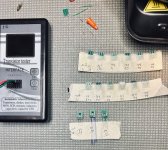
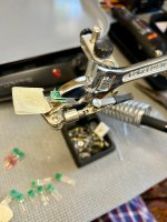
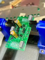
So I now have a bunch of dual K209s to experiment with. I’m quite proud of my PCB clamp. I played with different legs in my construction:
What would be the minimally invasive, noob-friendly recommendation on how to incorporate my equivalent-to-K170 dual JFET creations?
RTFM option: build a JFET matching rig based on threads and Nelson’s articles. Use that info to determine what resistors to change in the FE2022. Learn.
Hand-holding option : Use existing J113 CCS in the kits for Q3/Q4 and pop in K209 duals in for Q1/2. Does that make sense? Would that give me the presumed benefit of the K209s (driving Nelson’s ‘Curve A’ downward)?
Thanks for any guidance.
So I now have a bunch of dual K209s to experiment with. I’m quite proud of my PCB clamp.
I played with different legs in my construction:- Clipped leads from other projects (best)
- Solid CAT5 wire I typically use for input wiring (messy insulation)
- Solid 18G magnet wire (PITA varnish removal with dremel, which was better than flame removal)
What would be the minimally invasive, noob-friendly recommendation on how to incorporate my equivalent-to-K170 dual JFET creations?
RTFM option: build a JFET matching rig based on threads and Nelson’s articles. Use that info to determine what resistors to change in the FE2022. Learn.
Hand-holding option
: Use existing J113 CCS in the kits for Q3/Q4 and pop in K209 duals in for Q1/2. Does that make sense? Would that give me the presumed benefit of the K209s (driving Nelson’s ‘Curve A’ downward)?Thanks for any guidance.
Attachments
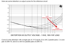
I suggest just using them in Q1 and Q2. I don't know whether they would make much difference in the distortion when used in the CCS.
I also suggest that you use pin sockets to mount them in the board. That way you can start with the J113s, measure the distortion, then switch to one pair of 2SK209 in Q1 and Q2, measure, and then add the second pair to Q1 and Q2, and measure again.
By the way I think with two J113 in Q1 and Q2, the distortion is Curve B.
Thanks, Ben!
I don’t have reliable methods for measuring distortion just yet. Still on the wish list to sort that out (either splurge on a QA403 or build a reliable rig for REW).
What I’ve settled on (for now) is the following:
I don’t have reliable methods for measuring distortion just yet. Still on the wish list to sort that out (either splurge on a QA403 or build a reliable rig for REW).
What I’ve settled on (for now) is the following:
- R1 Kit: This is slated to be incorporated in my BooLu OS build. Lowest distortion goal.
- Q3/4: kit J113s
- Q1/2: 2 of the 4 matched K369BLs I have with sockets
- No P1
- No R14
- R0 Kit: For stand-alone build or to be used with my unfinished MOFOs or another build (M2 OPS, etc.)
- Q3/4: kit J113s
- Q1/2: 4 of my K209 critters with sockets
Last edited:
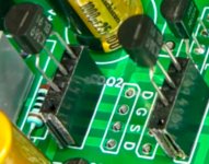
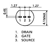
It looks like you have to rotate your 2SK369 180 degrees.
It may work anyways as source and drain are often interchangeable with JFETs (gate is middle pin).
It may work anyways as source and drain are often interchangeable with JFETs (gate is middle pin).
Attachments
Last edited:
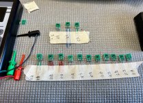
... another way of building paralleled 2Sk209 ... (just piggybacking them directly - bend the little pin stubs downwards and connect with a solder bridge to the stubs of the lower JFET) 🙂

... best regards, Claas
... best regards, Claas

So you ended up with only one jfet on each side of the input stage?
if you want to drive follower OSes and 8r speakers you will need to parallel the jfets.
I am using 4pcs in parallel on my pcbs.
if you want to drive follower OSes and 8r speakers you will need to parallel the jfets.
I am using 4pcs in parallel on my pcbs.
Interesting concept. Yes, just one K369 JFET (which I read as an equivalent to a pair of K170s) I am no circuit analyst, but from my layperson’s viewpoint, I thought that Q3-4-5 provided the oomph to drive the OPS and Q1-2 provided the input finesse. I certainly have the K209 critters to try in multiples for Q1-2, too. That would be thorough.
Q1 needs to drive R6, higher gm helps here because R6 is a low impedance load.
If manageable I would give a try to 4x k209 or 2x k2145 in place of one k369 because they are cheap and with a bit of patience easy to match.
If manageable I would give a try to 4x k209 or 2x k2145 in place of one k369 because they are cheap and with a bit of patience easy to match.
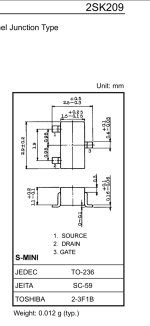
Top view.
Check out "orthographic projection": https://www.britannica.com/technology/orthographic-projection-engineering
Check out "orthographic projection": https://www.britannica.com/technology/orthographic-projection-engineering
 I finally found
 - Home
- Amplifiers
- Pass Labs
- DIY Front End 2022