
Your circuit is not as described in post #1,520 where you stated it had a single power supply with V- to Ground. Your schematic shows V+ and V- to the DIY FE 2022.
What is the result of this simulation? What is not working? Is the FE outputting a signal? What are the pertinent voltages? How is the bias voltage of the SIT adjusted?
What is the result of this simulation? What is not working? Is the FE outputting a signal? What are the pertinent voltages? How is the bias voltage of the SIT adjusted?
the TH51s part works fine in autobias with the 1.15hom resistance of the self , the schematic works fine with V+ and V- but doesnt work with the Grounding V- and put a capacitor in front of the Thf51s.
but if you say it works fine with the Diyaudiostore Boards it's my Sym that is wrong..
but if you say it works fine with the Diyaudiostore Boards it's my Sym that is wrong..
Thank You Ben now the sim works fine in LTspice , first time i see someone smarter than me 
do i need to do the same on the Board to go Single supply ?
do i need to do the same on the Board to go Single supply ?
It is already that way on the board.do i need to do the same on the Board to go Single supply ?
The board was designed specifically to work in either a single or dual supply configuration.
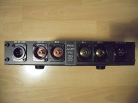
Hello, I'm looking for some help from fresh eyes. I assembled three FE2022 board to boost gain after my Schitt Syn. The FE2022s drive Cinemag transformers to generate balanced outputs. Some history: I initially bought 2 FE2022 v1r0 essentials kits, and then, a few months later 4 v1r1 essentials kits. I assembled all six this summer leaving the gain setting resistors out of 3 v1r1 boards since I have no idea what I'll want in them for use. The stack of three boards in my current 3 channel project has the two v1r0 boards and one v1r1 set to 4X gain.
As always, I was pressed for time getting ready to load up for BA2024, so my testing was quick and spotty. When I arrived and got set up on Saturday afternoon, I discovered that two channels (the v1r0s) worked fine, but the v1r1 was silent. I was able to complete the weekend running the L and R channels balanced through two bridged ACA Minis, and the center direct from the center channel output of the SYN. All worked well as the power needs of the derived center channel a much lower that the two sides.
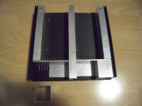
Naturally, the v1r1 board was at the bottom of the stack, so less easy to diagnose, so I left my troubleshooting efforts for my return home. Now that I've gotten into it, I've done the following:
1) Lifted the top and middle boards (v1r0) for access to the bottom.
2) Continuity checked the input and output chains to verify that the problem is not external to that board.
3) Tested voltages at appropriate points
Since all these efforts showed no flaws, and there are no signs of thermal distress on the board (or any heat when it was powered up), I then moved on to removing that board from the bottom of the stack and remounting it on the top. I desoldered all wires to the board and replaced several to do this.
I reassembled the whole assemblage with the SYN and tested that, and the situation remains the same: voltages good, continuity of inputs and output good, no heat or distress, no sound output. Other two channels remain fine.
I can easily put the final bits in one of my idle boards, but I thought I'd ask if I've missed something on the current v1r1 board. I lefte r13, r14, c6, and p1 unpopulated? Is there an error there? I've check all the soldering very closely, and concluded that there's an (A) bonehead error that I can't see or (B) a bad semi, which I don't really want to have to find).
A quick look will be much appreciated, but I'm happy to sub in another board should something not obvious to my eyes be the first thing one of you sees in the attached images
As always, I was pressed for time getting ready to load up for BA2024, so my testing was quick and spotty. When I arrived and got set up on Saturday afternoon, I discovered that two channels (the v1r0s) worked fine, but the v1r1 was silent. I was able to complete the weekend running the L and R channels balanced through two bridged ACA Minis, and the center direct from the center channel output of the SYN. All worked well as the power needs of the derived center channel a much lower that the two sides.
Naturally, the v1r1 board was at the bottom of the stack, so less easy to diagnose, so I left my troubleshooting efforts for my return home. Now that I've gotten into it, I've done the following:
1) Lifted the top and middle boards (v1r0) for access to the bottom.
2) Continuity checked the input and output chains to verify that the problem is not external to that board.
3) Tested voltages at appropriate points
Since all these efforts showed no flaws, and there are no signs of thermal distress on the board (or any heat when it was powered up), I then moved on to removing that board from the bottom of the stack and remounting it on the top. I desoldered all wires to the board and replaced several to do this.
I reassembled the whole assemblage with the SYN and tested that, and the situation remains the same: voltages good, continuity of inputs and output good, no heat or distress, no sound output. Other two channels remain fine.
I can easily put the final bits in one of my idle boards, but I thought I'd ask if I've missed something on the current v1r1 board. I lefte r13, r14, c6, and p1 unpopulated? Is there an error there? I've check all the soldering very closely, and concluded that there's an (A) bonehead error that I can't see or (B) a bad semi, which I don't really want to have to find).
A quick look will be much appreciated, but I'm happy to sub in another board should something not obvious to my eyes be the first thing one of you sees in the attached images
Attachments
One correction: I just noticed that the board versions are v0r0 and v0r1 not as I said above.
One addition: My power supply is providing 48.4 VDC to the boards, single voltage.
Skip
One addition: My power supply is providing 48.4 VDC to the boards, single voltage.
Skip
Thanks a bunch, Ben! Your reply suddenly made it appear in the schematic and the need for the jumper is obvious.
Skip
Skip
Currently populating the boards and wondering if I can power with 12-0-12 dual supplies ? From what I've read so far it should work but with an increase in measured distortion figures.
Asking as I have on hand a Studer900 supply board and a good transformer with 2x12v as required by the Studer.
Comments appreciated 🙂
Asking as I have on hand a Studer900 supply board and a good transformer with 2x12v as required by the Studer.
Comments appreciated 🙂
I don't know whether the distortion difference would be noticeable.
The biggest difference would be the maximum output voltage. With a power supply of 24V total, the maximum output voltage would be around 8Vrms.
The biggest difference would be the maximum output voltage. With a power supply of 24V total, the maximum output voltage would be around 8Vrms.
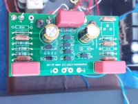
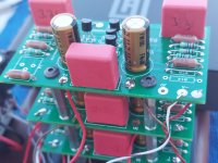
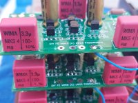
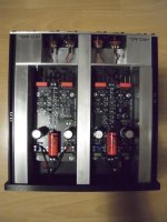
Hello FE2022-builders,
this wasn't a lazy sunday... Today I mounted my 4th version of the FE2022 as a preamp into its case.
It will be a 3-case construction: case1 for input- and volumecontrol / case 2 for the preamp-boards / case 3 for the PSU.
Completely dual mono.
The amp section was built with 2 pairs of TOSHIBA 2SK209GR (closely matched)per channel. In the second stage I used a Diodes / ZETEX FZT 951.
A lot of Vishay/Beyschlag MELF -resistors. And some SUSUMU - resistors in the direct path (R1 / R4 / R5). On my pcbs I have spots for through hole and SMD-parts - makes it very versatile.
Have to build the PSU into the case...
And - it sounds great!
Cheers
Dirk 🙂
Attachments

- Home
- Amplifiers
- Pass Labs
- DIY Front End 2022