Thanks for the revision details Nelson - is the new pcb still the same size with mounting holes on same centres?

I still have a bunch of 2SK170 and LKS170, would they do a (better) job than the SXJ113?
Cheers,
Dan
Cheers,
Dan
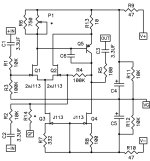
OK everybody, gird your Grids, here comes Version 1 rev 1:
I have added some additional optional parts. As you can see from the schematic there is
now an R13, R14, P1 and C6.
R13 is a low value degeneration resistor for Q5. In actual testing with the KSA992 I did
get a bit lower distortion with a 10 ohm value. Not a big deal, but it does help get me
down to sub .001% distortion numbers, even with the J113 input fets. Accompanying
that is a slight increase in R6 to 750 ohms. If you want to lowest thd numbers, use a
supply as high as +/-24V or 48V single-ended.
However, I have also included a 1 Kohm pot which can replace R6 in case you want to
make the small sacrifice of distortion vs DC offset in DC coupled applications. Just turn
the pot until the DC is zero, and adjust it again after warmup. Remember to leave R6 off.
R14 is an optional resistor if you want to take your feedback from an output stage. You
can leave R4 in if you want some local feedback. Or not. Remember that R14 looks at an
output node which might be at a different DC potential, and it might require an external
blocking cap in such a case.
C6 is a lag compensation cap in case you need one. 33 pF will not have much effect on
the distortion vs frequency plot, 100 pF will increase the thd a bit at 20 KHz, but still have
acceptable performance. When you have a weird load or take feedback from an output
stage this might come in handy.
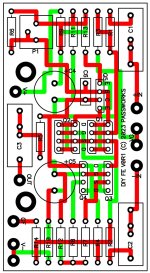
PC board is larger by 1/4 inch, this should not be a problem. Keep in mind that these are
all options - you can easily build the original, just put a jumper across R13 with a leftover
resistor lead.
Kits are being packed up, and if they sell out, there are more coming....

I have added some additional optional parts. As you can see from the schematic there is
now an R13, R14, P1 and C6.
R13 is a low value degeneration resistor for Q5. In actual testing with the KSA992 I did
get a bit lower distortion with a 10 ohm value. Not a big deal, but it does help get me
down to sub .001% distortion numbers, even with the J113 input fets. Accompanying
that is a slight increase in R6 to 750 ohms. If you want to lowest thd numbers, use a
supply as high as +/-24V or 48V single-ended.
However, I have also included a 1 Kohm pot which can replace R6 in case you want to
make the small sacrifice of distortion vs DC offset in DC coupled applications. Just turn
the pot until the DC is zero, and adjust it again after warmup. Remember to leave R6 off.
R14 is an optional resistor if you want to take your feedback from an output stage. You
can leave R4 in if you want some local feedback. Or not. Remember that R14 looks at an
output node which might be at a different DC potential, and it might require an external
blocking cap in such a case.
C6 is a lag compensation cap in case you need one. 33 pF will not have much effect on
the distortion vs frequency plot, 100 pF will increase the thd a bit at 20 KHz, but still have
acceptable performance. When you have a weird load or take feedback from an output
stage this might come in handy.
PC board is larger by 1/4 inch, this should not be a problem. Keep in mind that these are
all options - you can easily build the original, just put a jumper across R13 with a leftover
resistor lead.
Kits are being packed up, and if they sell out, there are more coming....
Attachments
Last edited:
R13 with adjustable P1, allow the "Lender" Q2-Q6 connection. Then the "Lender" connection shifts the open-loop Bode Plot to the northeast. Then the shifted Bode Plot gives lower distortion, closed-loop. Which is pleasing!
Whoops, thanks.
R13 with adjustable P1, allow the "Lender" Q2-Q5 connection. etc
R13 with adjustable P1, allow the "Lender" Q2-Q5 connection. etc
DAC with/XLR to ACP+ via FE2022 as unity gain w/dual rail PSU (18-24v??). Is this the correct wiring, gain setting and PSU voltage?
Please comment.

Please comment.
Looks like a fine example of a discrete high performance balanced to single ended converter to me.
Image 1 shows Pa's latest iteration, for reference. Since option to DC couple was provided i bypassed the caps so we can see the full spectra on the FFT. A pretty decent performer, considering 10Vpp. One thing i notice is the bias point is now 6.2mA instead of 9mA, so that's what we'll go with.
 Then we can take EUVL's idea from post 568 for using the KSA992's complementary, and thermally coupling it to account for any tempco and improve DC offset stability
, play around a bit with some ideas from the thermal distortion paradigm and cascoding the VAS linearises it, then cascoding this again to reduce thermal Vbe variations we arrive at image 2.
 Quite a nice performance gain for a few more parts. It decreases the 2nd harmonic by a bit, but almost halves 3rd harmonic, "improving" the profile significantly (20db vs 13db difference between H2/H3). It also changes the H2 phase to negative, and as an added bonus, if you are to believe it, it also reduces TIM.
If we do the same thing on the NPN side, an even greater improvement, h2 drops by 5db but H3 halves yet again, now we have 24db difference between H2 and H3. Still retaining the negative phase H2.

I tried the idea from Erno's jfet article (figure 14B) on cascoding to reduce Ciss, here Q11 and Q13, though this resulted in slightly worse performance no matter which fet i tried or introduced local feedback with source resistors or not, not sure why.

I left input jfet's as J113's for comparison sake, but will build with 2x2 2sk209GR's, which improves things yet again. By using a couple more transistors, we end up with 4x lower distortion and a better harmonic profile, sayz the sims? Seems too simple, now i wait for someone actually smart to tell me what the catch is.
 Here is one just for fun. At 1.4Vrms (a normal level you're likely to use), it produces almost nothing but H2 (-98db), H3 is -137db. Which is a 40db difference as well.
 Thanks Pa, thanks EUVL, thanks ZM (no particular reason, but he's a pretty cool fella')
, play around a bit with some ideas from the thermal distortion paradigm and cascoding the VAS linearises it, then cascoding this again to reduce thermal Vbe variations we arrive at image 2.
If we do the same thing on the NPN side, an even greater improvement, h2 drops by 5db but H3 halves yet again, now we have 24db difference between H2 and H3. Still retaining the negative phase H2.
I tried the idea from Erno's jfet article (figure 14B) on cascoding to reduce Ciss, here Q11 and Q13, though this resulted in slightly worse performance no matter which fet i tried or introduced local feedback with source resistors or not, not sure why.
I left input jfet's as J113's for comparison sake, but will build with 2x2 2sk209GR's, which improves things yet again. By using a couple more transistors, we end up with 4x lower distortion and a better harmonic profile, sayz the sims? Seems too simple, now i wait for someone actually smart to tell me what the catch is.
Hi Dendrobium, LTSpice simulations are a great tool, and I use them all the time. However, my measurements of my built DIY FE 2022 measured much better than the simulations that I tried, and similarly much better than the first simulation of your post. I built mine from the kit with no substitutions, with low cost parts, and the only change I made was to up the voltage to +62V. You can see the FFT results in post #647 (Post #647).
The output voltages were Vrms. By the way, you wrote that your output voltage was 10Vpp, but your LTSpice output showed 10Vp, or 20Vpp, equal to 7.07Vrms. So if you compare your LTSpice result from your first simulation to my measurements at 5Vrms and 10Vrms, you will see that measured results of my build were quite a bit lower than your simulations, and my simulations. In fact my measured results were quite close to Nelson's published results (I believe his voltages are Vp).
Another point, I believe when LTSpice shows the 2nd harmonic distortion "Normalized Phase" as +90 degrees, that is what Nelson would call negative 2nd harmonic. His oscilloscope shot of the distortion in his article showed the DIY FE 2022 producing negative phase 2nd harmonic distortion.
Fair points, and i agree your measurements looks very good. If we have pretty good evidence that in this case the accuracy of the simulation does not correspond perfectly to reality, i wonder still is precision is good? Meaning, will relative gains in sim translate into relative gains in real world, even if sims =/= real world in absolute values. I think perhaps that was always kind of a bit of a weak spot, and strong spot respectively, with spice simulations..it is reasurring to know anyway that real world is better than sims in this case, anyway. And good catch with the 10Vpp thing as well, my misnomer. Interesting point with the phase as well, i must have glossed over the fact that the original circuit is already supposed negative phase, implying now Spice notation is reverse to Pa notation, so now it implies it would be positive phase.
Btw, i would note that this amp scales very well with increased voltage, and at +-32 (like +64) and no other changes i get half the distortion on the original schematic, if you built an earlier version with 9ma bias instead of 6.2m, the number are different yet again so there's realistically a lot of things to play with here. I just wanted to try to reveal some topological changes.
Btw, i would note that this amp scales very well with increased voltage, and at +-32 (like +64) and no other changes i get half the distortion on the original schematic, if you built an earlier version with 9ma bias instead of 6.2m, the number are different yet again so there's realistically a lot of things to play with here. I just wanted to try to reveal some topological changes.
SureHi Dendrobium, could you please share your last LTspice project file?
Attachments
Last edited:
- Home
- Amplifiers
- Pass Labs
- DIY Front End 2022