Hi Lars
what is the output impedance of your schematic? If I'll build it, I have to omit the 7k resistor (R5)?
what is the output impedance of your schematic? If I'll build it, I have to omit the 7k resistor (R5)?
Hey Tolu,
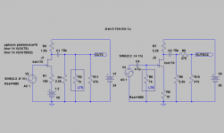
The 7k symbols your Lightspeed😉. Had to put it there to check the circuits behaviour with the IRL load. You can add a 470k to keep C1 uncharged with nothing connected.
Also C1 could be tailored to suit your needs, 10u gives you a -3dB of ca 2Hz with your Lightspeed. You could as well use a 4,7u, but not less!
Have not checked Zout but it should be well below 100ohm, ~1/Gm.
Tolu said:Perhaps Lars' finds a trick to use only one JFET
If you really want just one jFet you can still use the circuit I linked to in post 31. The dac board we're discussing in this thread has capacitor-coupled outputs - so no problem.
Lars' direct-coupled solution is probably +😎 though.
revintage said:Hey Tolu,
The 7k symbols your Lightspeed😉. Had to put it there to check the circuits behaviour with the IRL load. You can add a 470k to keep C1 uncharged with nothing connected.
Also C1 could be tailored to suit your needs, 10u gives you a -3dB of ca 2Hz with your Lightspeed. You could as well use a 4,7u, but not less!
Have not checked Zout but it should be well below 100ohm, ~1/Gm.
I will try your schematic as soon as I get my DAC board that I ordered tonight. 🙂
I just need a nice circuit for a suitable PS. With 30V I have to discard my battery power approach. Have you simulated lower supply voltages in respect of distortion, too?
Hi guys,
The 1 transistor solution is to place the Lightspeed directly after the DAC and the gainstage after the volumecontrol.
This sadly leaves us with 2 caps in the chain. The DAC will not have any problems driving the VC(albeit there will be some more signalloss as the AC-load is now 620ohm) but the output cap should be enlarged to 5-10u.
The FET after the VC should then by locally feedbacked to have a gain of ca 12-15dB. Something like the JFET BOZ but tailored to fit Tolus combination.
So you have to choose between two FETs/ one cap or one FET/two caps. I personally would choose the first.
Tolu, what is your available battery B+?
revintage said:Tolu,
Are you restricted to 16,8V? Can get max 3x gain with that. So maybe 24V could be doable?
20 NiMH cells seems a little bit complicated to me. Than I would prefer a normal PS. Do you have a nice, simple circuit, perhaps with a simple LM317?
I´d suggest a notebook type of 24V SMPS with additional LC HF-filtering. For evaluation purpose you can skip the additional filtering. There are easy-to-find adjustable units for about 20EUR.
revintage said:I´d suggest a notebook type of 24V SMPS with additional LC HF-filtering. For evaluation purpose you can skip the additional filtering. There are easy-to-find adjustable units for about 20EUR.
You mean ...
...as battery charger? Than you need a little bit more not to kill the brave NiMH cells.
... as audio PS? I always thought SMPS is evil.
 ?
? 
Hey Lars
you are very quick! Thank you very much!
I like the left circuit more!
Is it right that the DAC output is connected directly to the gate of the JFET? No series resistor between? And no EC mod anymore?
you are very quick! Thank you very much!
I like the left circuit more!
Is it right that the DAC output is connected directly to the gate of the JFET? No series resistor between? And no EC mod anymore?
Off course you should have the EC mod with 680 V and 3V bias😉 . Its the heart in this circuit.
The symbol for signal that says source is 680ohm with 2,2V DC.
You could add a gatestopper if you get stability problems.
Will do a new schematic to clarify. Also note this circuit should be soldered into the DAC as an integrated part.
The symbol for signal that says source is 680ohm with 2,2V DC.
You could add a gatestopper if you get stability problems.
Will do a new schematic to clarify. Also note this circuit should be soldered into the DAC as an integrated part.
using 8V supply for 1543
In order to get around 2VRMS, with 8V supply and 2.7K I/V resistor, I guess need 8.4V reference battery supply, anyone can confirm?
with 8V supply, we can reach 5V peak-peak (8-1.2-1.8), so middle point is 1.8+5/2=4.3V, with 0.015MA over 2.7K, the battery is 4.3V + 0.0015*2700 = 8.35
In order to get around 2VRMS, with 8V supply and 2.7K I/V resistor, I guess need 8.4V reference battery supply, anyone can confirm?
with 8V supply, we can reach 5V peak-peak (8-1.2-1.8), so middle point is 1.8+5/2=4.3V, with 0.015MA over 2.7K, the battery is 4.3V + 0.0015*2700 = 8.35
Got my DAC from DIYHIFI today. Just have a 6VA wall wart which runs at 9V to the DAC.
I played 2 CDs so far (Diana Krall - The girl in the other room, Katie Melua - Piece by piece).
How does it sound? Retro I would say. Limited dynamics and limited top end. I miss the sparkling highs and the room info. I think time didn't stand still in DAC development. Compared to my favorite player with BB PCM1607K DAC that is another league. The BB is precise and musical with much air and room. The Philips is ... old? Perhaps it improves a little bit. I compared it with my old Denon DCD-560 with 2 OPA2134 in the output stage. The Denon wins by length.
So as everytime I think, you get what you pay for! 😀
Tolu said:Got my DAC from DIYHIFI today. Just have a 6VA wall wart which runs at 9V to the DAC.
I played 2 CDs so far (Diana Krall - The girl in the other room, Katie Melua - Piece by piece).
How does it sound? Retro I would say. Limited dynamics and limited top end. I miss the sparkling highs and the room info. I think time didn't stand still in DAC development. Compared to my favorite player with BB PCM1607K DAC that is another league. The BB is precise and musical with much air and room. The Philips is ... old? Perhaps it improves a little bit. I compared it with my old Denon DCD-560 with 2 OPA2134 in the output stage. The Denon wins by length.
So as everytime I think, you get what you pay for! 😀
I have one of these....Yes it lacks the high end sparkle of the modern DACs but it does have a nice full bodied mid range. I upgraded the output coupling caps and this definitely improved the sound.🙂
- Status
- Not open for further replies.
- Home
- Source & Line
- Digital Line Level
- Diy-dac 1543