USB Curve Tracer
USB Curve Tracer.
I started a new thread about this.
Didn't want to impinge on the project that's in progress here.
USB Curve Tracer.
I started a new thread about this.
Didn't want to impinge on the project that's in progress here.
Where is it? Could you post a link to it please?
Edit: I found it, it's here http://www.diyaudio.com/forums/equipment-tools/158480-usb-curve-tracer.html#post2044632
Edit: I found it, it's here http://www.diyaudio.com/forums/equipment-tools/158480-usb-curve-tracer.html#post2044632
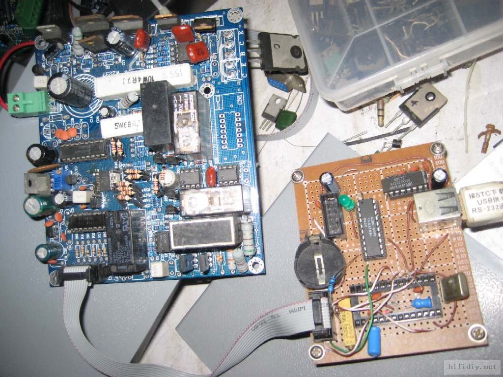
We tested one example from Locky_z. We also got the documentation including description of the circuitry, with a lot of clever thoughts. It is also one of the very few curve tracer available to DIY'ers which can provide test current up to 3A. Most others published on the net and/or available on the net (e.g. that from Elektor) can only test with say 20mA or so, i.e. no use for power devices.
As there is no uP on the board, the entire measurement procedure is controlled by the PC, which explains the need for parallel port. We did have some problems loading and running the software on English Windows, and used a PC with Chinese Windows in the end. But I think this is solvable.
Once set up, it is pretty easy to use, very versatile, and does pretty much everything we want. It is a bit of a shame that the creater has limited his choice of components due to cost considerations. And at that selling price, one can probably understand. The PCB layout is not brilliant, and some of the components are rather marginally dimensioned and suffer from thermal drifts. So if you do matching within minutes, it is probably good enough. If you want to compare measurements with months or years in between, there is quite a bit of refinements required.
We are, for our own purpose, working on improved hardware and PCB layout, and shall include active temperature control of the DUT (adjustable from room temperature to 100°C). Quite a bit of work, so it will take a while. And above all, it is someone else's intellectual property. So whether it will be made available to the public eventually will not be our decision.
But it is a very handy piece of kit, cleverly done, and have great potential if we allow the use of much better components (e.g. reference resistors with low thermal coefficients). So congradulations to Locky_z for the great work.
😉
Patrick
the kit include circuit,you can layout the PCB.
there are some value in circuit may be diffent,and you can change it from software.
the English Version software is doing,
once finish ,i will send you to try.
but I can't not send to "wkypb@hotmail.com" beause the server filte it as "spam-like" .
there are some value in circuit may be diffent,and you can change it from software.
the English Version software is doing,
once finish ,i will send you to try.
but I can't not send to "wkypb@hotmail.com" beause the server filte it as "spam-like" .
Thank you for your input.
You can send me a private email through this forum by clicking on my nickname.
Then I shall reply you from there.
Looking forward to your English version.
We'll give you our feedback. If you need further help, just let us know.
Patrick
You can send me a private email through this forum by clicking on my nickname.
Then I shall reply you from there.
Looking forward to your English version.
We'll give you our feedback. If you need further help, just let us know.
Patrick
Re EVAL
>>>>In your circuit board and schematics, you are using a 10 pin connector to connect to the PC parallel port. Can you tell me the pin assignment that corresponds to the 25-pin D-sub connector of the PC (i.e. which pin from the 10 pin connector goes to which pin in D-Sub) ?
==========================
if you use another pin assignment,you must change the software option of "端口定义"
>>> Also in the current generator circuit for the base current, SW3 is connected to Vref in current mode according to the schematics. Should that not be Vref / 2 if you want to generate both positive and negative current without further switching ? If I understand correctly, J5B only switch between voltage out and current out, but not positive or negative current.
================
the current generator circuit As described
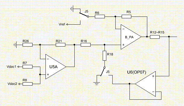
when J5 switch as above,B_PA is work in voltage out
if J5 is another size, B_PA & U6 is V/I circuit, I=(V5a-Vref)*K/R12
Here have some attention:
when U5a out is less Vref,then the B_PA out current direction is pull,mean is "Negative" current.But base on GND ,all current is positive.
Beasure the DAC(M62359) can output 0~11.5V, V5a is out 0~13V,Vref=6.5V is the best. but I lazy,I instead of it with Vref.
>>>>One more question for the DAC. If I want to use AD5308 instead (cannot get M62359, already obsolete), I should connect the SYNC pin of AD5308 to Pin4 of the 10-pin input connector, and LDAC pin to Gnd; is that correct ? Thanks and best regards,
====================
The CT need more 14bit step DAC, but no need high precision or linearity DAC,so i use two 8 bit DAC out mix , as a 14bit DAC.
If change DAC,the source code must change ,becase M62359 control byte is no same with AD5308.
>>>>In your circuit board and schematics, you are using a 10 pin connector to connect to the PC parallel port. Can you tell me the pin assignment that corresponds to the 25-pin D-sub connector of the PC (i.e. which pin from the 10 pin connector goes to which pin in D-Sub) ?
==========================
if you use another pin assignment,you must change the software option of "端口定义"
>>> Also in the current generator circuit for the base current, SW3 is connected to Vref in current mode according to the schematics. Should that not be Vref / 2 if you want to generate both positive and negative current without further switching ? If I understand correctly, J5B only switch between voltage out and current out, but not positive or negative current.
================
the current generator circuit As described
when J5 switch as above,B_PA is work in voltage out
if J5 is another size, B_PA & U6 is V/I circuit, I=(V5a-Vref)*K/R12
Here have some attention:
when U5a out is less Vref,then the B_PA out current direction is pull,mean is "Negative" current.But base on GND ,all current is positive.
Beasure the DAC(M62359) can output 0~11.5V, V5a is out 0~13V,Vref=6.5V is the best. but I lazy,I instead of it with Vref.
>>>>One more question for the DAC. If I want to use AD5308 instead (cannot get M62359, already obsolete), I should connect the SYNC pin of AD5308 to Pin4 of the 10-pin input connector, and LDAC pin to Gnd; is that correct ? Thanks and best regards,
====================
The CT need more 14bit step DAC, but no need high precision or linearity DAC,so i use two 8 bit DAC out mix , as a 14bit DAC.
If change DAC,the source code must change ,becase M62359 control byte is no same with AD5308.
Attachments
Being translate to English Version
At the space time ,I also develop the USB version ,
I use C8051F330+PL2303HX link to the old "parallel port Version CT"
PC software through USB communicate with C8051F330, and control the old "parallel port Version CT" measure.
USB version the most measure speed is 86 point/sec.
If you want more precision,then slow down to 9 point/sec(66 times sample and average)
The image below is 66 times/18 times/ 6 times/ 1times sample to measure 2sc3281's hfe-ic curve.
Attachments
Dear Chung,
Thank you for the answers.
M62359 is no longer available (maybe still in China but not anywhere else).
We need to use a newer DAC, like the AD5308.
The USB version is interesting, but I think parallel port is also fine.
Any progress with English software ?
Can we help you ?
Mark will contact you by email.
Patrick
Last edited:
I, for one, would like to express my thanks for a USB version. Parallel ports have been hard to come by for a few years. I'm down to one parallel port PC these days-and it is truly ancient (I use it, to run a light controller I built about a dozen years ago, that runs off, you guessed it, the parallel port).
My plan would have been to use a USB to parallel adapter with this curve tracer-although I wonder if that would actually work -can anyone speculate?
Terry
My plan would have been to use a USB to parallel adapter with this curve tracer-although I wonder if that would actually work -can anyone speculate?
Terry
You need something like this :
EPP Parallel PCMCIA Cards by Quatech
There is too much performance loss using USB (speed of measurement).
Patrick
EPP Parallel PCMCIA Cards by Quatech
There is too much performance loss using USB (speed of measurement).
Patrick
Thanks for the recommendation.
BTW, how much time are we talking about to take a 'good' measurement?
I'm curious as to why it would be so slow. Is it the throughput of the USB (480 Mbit/s~57 MB/s)? Or is USB just architecturally flawed?
Thanks for any info you can provide.
Terry
BTW, how much time are we talking about to take a 'good' measurement?
I'm curious as to why it would be so slow. Is it the throughput of the USB (480 Mbit/s~57 MB/s)? Or is USB just architecturally flawed?
Thanks for any info you can provide.
Terry
Then if I understand you correctly the USB version takes > seconds and so causes the device to heat up. Correct?
Terry
Terry
The original Curve track software use 'bit' to to simulate SPI protocol through Parallel ports
But USB is only support frame transmission ,The minimum frame is 2ms,
If I send a 8 bit SPI protocol ,I must send 8 frame at least.It will be very slowly.
So, If use USB,you must use a MCU outside, and receiver macro command and send SPI protocol to control ADC/DAC. This mean you must develop two set software, one is PC,one is MCU fireware
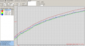
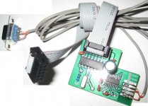
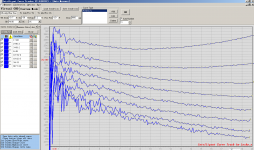
RS232 adapter already complete

and English Version have done.

Above picture is measure 2SA970 hfe-Ic curve track on different Sample.
the bottom curve is 1 times sample
another curve is from 2 3 6 10 18 34 66 times sample.The more sample,then measure speed is slow.
and English Version have done.
Above picture is measure 2SA970 hfe-Ic curve track on different Sample.
the bottom curve is 1 times sample
another curve is from 2 3 6 10 18 34 66 times sample.The more sample,then measure speed is slow.
Attachments
- Status
- Not open for further replies.
- Home
- Amplifiers
- Solid State
- DIY Curve Tracer for PC