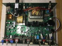
Frontpanel/Frontboard sandwich ready. Follow the instructions to the letter! It helps if you can make a few distance tools of 18mm length, e.g. from screw posts. Fit them between the PCBs and clamp the boards together. That way you ensure an even 18mm distance everywhere while fitting and soldering switches and pots. I used threadlocker loctite blue to secure the distance nuts on the switches because the tend to shift.


First of all, I have to apologize because due to a problem, I did not see the new postings here.
I also did not get an email when new postings were made. Today I got them all in one go. Don't know why...
This is the reason that I missed the requests for the 10Set BOM's and I did not reply to questions. Sorry!
I did now post the PCBWAY BOM for the Main board, but I don't have the one for the Front board.
I've asked Mark to send it to me so I can post it.
Last edited:
So, here’s an update. The unit is ready for the first test, tomorrow…
I also wrote a PoP Python —offline— frontend. Still needs Load and Save functionality as well as sending setup to Rigol DS1000 osci. If you want to see how it’ll look you need Python 3.9 min. as well as QT 5.15/6.41 installed.
Plan is to give a hands on support to correct setup of the CT unit as well as the oscilloscope and a database of DUTs and an import function of the characteristic curves. Lots todo…
Attachments
Looks good! Thanks for the pics.So, here’s an update. The unit is ready for the first test, tomorrow…
I also wrote a PoP Python —offline— frontend. Still needs Load and Save functionality as well as sending setup to Rigol DS1000 osci. If you want to see how it’ll look you need Python 3.9 min. as well as QT 5.15/6.41 installed.
Plan is to give a hands on support to correct setup of the CT unit as well as the oscilloscope and a database of DUTs and an import function of the characteristic curves. Lots todo…View attachment 1126827
I have no time to see what you did with the software, I'm fully into another project.
Quote [Mainboard Installation Instructions]: 67. Turn on the power and verify that you have a negative going triangle waveform and that you can change the amplitude with the 100K potmeter. If you do, we have a working Main board. [/]
Yes we do!

Next steps: Board interconnects.
Note: The whole thing looks awfully complicated. Surprisingly it is not. Thanks to the excellent installation and setup instructions it is rather medium complex for anyone able to solder 0805 SMD parts.


Yes we do!
Next steps: Board interconnects.
Note: The whole thing looks awfully complicated. Surprisingly it is not. Thanks to the excellent installation and setup instructions it is rather medium complex for anyone able to solder 0805 SMD parts.
Attachments
That looks great and looks very familiar...Quote [Mainboard Installation Instructions]: 67. Turn on the power and verify that you have a negative going triangle waveform and that you can change the amplitude with the 100K potmeter. If you do, we have a working Main board. [/]
Yes we do!View attachment 1128399
Next steps: Board interconnects.
Note: The whole thing looks awfully complicated. Surprisingly it is not. Thanks to the excellent installation and setup instructions it is rather medium complex for anyone able to solder 0805 SMD parts.View attachment 1128400View attachment 1128402
You're almost there I assume.
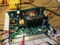
Alive!

Current limiter works…
 All interboard connections done

I left the BNC connections for the time being just in case I have to take the sandwich out again to fix something revealed during calibration.
I also attach a preliminary picture of the frontend I am working on

Next step: Calibaration
Current limiter works…
I left the BNC connections for the time being just in case I have to take the sandwich out again to fix something revealed during calibration.
I also attach a preliminary picture of the frontend I am working on
Next step: Calibaration
Looks good! Well done...Alive!View attachment 1129564
Current limiter works…View attachment 1129565All interboard connections doneView attachment 1129563
I left the BNC connections for the time being just in case I have to take the sandwich out again to fix something revealed during calibration.
I also attach a preliminary picture of the frontend I am working onView attachment 1129566
Next step: Calibaration
Ok, done. Calibration went, as far as I am able to judge, successfully.
Here’s a stress test I did with the unit on a 2N4401, 6VCE, 350mA IC, IB 200uA x 7 steps. With the maximum step delay the DUT does not get hot! All other functions verified as well. I am not so sure about the Offset, i have to check with the developer…


Here’s a stress test I did with the unit on a 2N4401, 6VCE, 350mA IC, IB 200uA x 7 steps. With the maximum step delay the DUT does not get hot! All other functions verified as well. I am not so sure about the Offset, i have to check with the developer…
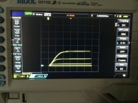
Ok, Offset function verified…
BS170, VGSth=0.8-2.1V @ 7 x 500mV VGS steps, with and w/o offset applied. You see it coming on at about 2V (3 out of 7 steps visible). Without offset you don’t see the first 4 steps! In this case the offset was set to about 2V. Also this thing (DUT) is blasting out 700mA at VGS 3.5V / VDS 6V. Thanks to the step delay function of the device the DUT does not get hot at all! Wonderful…
Next steps: CT Python Frontend, Rigol DS1000 Control and transistor database.
Attachments
Last edited:
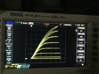
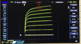
…ok one more. Just verified the 2A max output. Can go upto 35V/2A. Curve attached is from a BD244, IB: 5-35mA, VCE: 6V (to limit dissipation). With step delay activated DUT doesn’t get hot although it is at 12W!

hFE: IB 5mA=130, 10mA=100,…
hFE: IB 5mA=130, 10mA=100,…
Last edited:
Looking really nice ... DIY Audio store should put this project in the store ... not many options out there for very affordable curve tracers.
Very impressive progress tubekiddo
Very impressive progress tubekiddo
Thank you! Very much appreciated!Looking really nice ... DIY Audio store should put this project in the store ... not many options out there for very affordable curve tracers.
Very impressive progress tubekiddo
For an old man like me these projects are very rewarding when they finally work. I mean it was 250+ SMD parts soldered by hand, lol
The project is open source. Paul did provide excellent help. The BOM can use some tweaking so does the calibration instructions. But overall it’s manageable and IMHO worth the effort. If anyone needs any info just ask…
SMD populated PCBs would be preferable for the ‚masses‘. And I guess we want to keep it open source! The device is being used at a university teaching students.
Last edited:
Here’s a document from Toshiba explaining the dV/dt effect on Mosfets (happens on BJTs too), background and countermeasures. I think it’s caused by so called Miller capacitance (collector - base capacitance). I am not an expert!
https://toshiba.semicon-storage.com/info/application_note_en_20180726_AKX00069.pdf?did=59464
A few posts up is a picture attached from me showing an perfect symmetrical triangle🙂
My conclusion: for fast switching applications I’d seek a DUT with minimum ‚deflection‘ or choose the right operating point.
Last edited:
That effect is explained in the blogs for the instrument. It is indeed mostly a function of self heating/cooling of the DUT and the gain change caused by it.Curious question: What causes the discrepancy between the up and down sweep? Is the triangle wave not quite symmetrical?
Tom
That was my second guess but I didn't think it would cause that much of a difference. Thanks for the explanation.
Tom
Tom
That's like saying, "the oscilloscope showed a perfect sine wave". Never mind that even THD of a few percent is nearly impossible to see on an oscilloscope. A slight curvature of the triangle wave would be enough to cause the difference seen in the curve trace display.A few posts up is a picture attached from me showing an perfect symmetrical triangle🙂
Tom
Would it? I'd think the oscilloscope measures the true voltage of the triangle signal and puts the dot at the correct x-axis position of the display. Or am I missing something?A slight curvature of the triangle wave would be enough to cause the difference seen in the curve trace display.
- Home
- Design & Build
- Equipment & Tools
- DIY Curve Tracer (analog)