Hello all, new to the forums.
I was wondering if the attatched schematic would work as an amplifier for a 5W 8ohm speaker. The application of this amplifier is for a bluetooth portable speaker.
Im not aaking for great aound quality, butnif anyone can give me advice on how to makemit better I will consider it.
Thanks!
I was wondering if the attatched schematic would work as an amplifier for a 5W 8ohm speaker. The application of this amplifier is for a bluetooth portable speaker.
Im not aaking for great aound quality, butnif anyone can give me advice on how to makemit better I will consider it.
Thanks!
Attachments
Class A and portable generally don't go together well. The heatsink will be as large as a small speaker box by itself. Look into a small chip amp instead.
It should work, but its a bit to simple to be very good. If you want Class A then you may as well aim a little higher, otherwise a simple chip amp as jerluwoo mentions will be far better.
Check out the original JLH69 amp. There are loads of threads about that. Its very simple and very good.
Check out the original JLH69 amp. There are loads of threads about that. Its very simple and very good.
Attachments
Portable means battery powered, or at least it does to me anyway... Class A is probably the one you should avoid the most because of it's very low efficiency. But even if you will not power it from batteries, still as it has been said, the heatsink should be quite large. I think the best way to go, especially if you intend to power the amp from batteries, is class D, that way you get the most power from the energy invested in it, and thus a small heatsink ( or rather very small in some cases, or none at all at low power ).
Cheers.
Cheers.
Can anyone point me in the right direction to a simple class d amp, I would like to use discrete components of possible.
I know that class d uses a own signal, is there a possibility i could use an atmega328, like an ardu8no or an attiny chip?
You'll get a much better idea of what class D is and why discrete component builds are impractical here: Class D - diyAudioCan anyone point me in the right direction to a simple class d amp, I would like to use discrete components of possible.
Class D owes it's efficiency to the way the power stage is operated, it is sort of a buck sincron regulator, it uses a square carrier wave of high frequency, with it's duty cycle modulated by the audio signal on the imput, the power switches on the output are always either fully ON or fully OFF, thus power loss is very small, the musical signal is filtered out before the speaker with the help of an LC low pass filter.
That would be the very short version of it, building a class D power amp only with discrete components is a tough order, but i think there should be a class D chip amp suited for your application, you first need to work out the fine details, how do you intend to power it up, what speaker impedance would you use, is size an issue, and other stuff like that...
That would be the very short version of it, building a class D power amp only with discrete components is a tough order, but i think there should be a class D chip amp suited for your application, you first need to work out the fine details, how do you intend to power it up, what speaker impedance would you use, is size an issue, and other stuff like that...
And don't confuse class d with digital. Most class d amps are completely analog. They switch, but nothing is quantized (no bits or clock involved)!
Care should be taken when designing the output inductor, the IC's datasheet should help you in selecting a good size, but care should be taken in selecting the core it's self, iron powder cores are maybe cheaper and easier to procure, and they do give off less EMI radiation but they are prone to more power loss in the core, low permeability cores like for example -2 from Micrometals are best, they assure a lower working temperature, they do require more turns for the desired inductance, but for low power applications like yours, you do not have to worry about copper losses. A better solution are gapped ferrite cores, with them, the core losses are much lower, but they give off more EMI and also may be harder to find. It's your choice.
Cheers.
Cheers.
Thanks for the feedback, I know that all of you have been telling me to do a different design or to use a chip, but I I am going to use the schematic I posted. I am not going for quality, just a crude working example, haha.
But the last question that I have is can I use an input voltage of 12v instead of 24v, if so are there any drawbacks? Thanks
But the last question that I have is can I use an input voltage of 12v instead of 24v, if so are there any drawbacks? Thanks
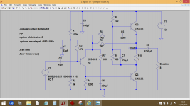
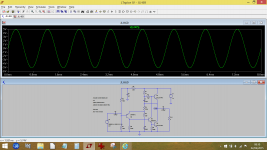
I've tried simulating this simple amp and at a basic level can not get it to work using common device models. The reason I suspect is that the BD439 devices can have quite a high current gain, but that's not guaranteed looking at the data sheet.
This all smacks of a poorly thought out design which should work with pretty much any generic parts.
Check the circuit over and make sure I haven't made a silly mistake copying it over. Adjusting R2 can not bring the mid point volts down from around 22 volts. Even shorting Q1 out still can not supply enough base current via R6 to turn on Q3. I tried several different models of common power devices and all gave similar results. C5 looks a little 'unlikely' too.
Now compare the JLH69 design I mentioned. No comparison 🙂
Attachments
As you can tell, I don't know really anything about this stuff.
So can I use some of the parts that I have from my schematic and use them in the jlh69.
I have one nte159 pnp transistor, 2 nte184 npn transistors. I also have a couple small signal npn transistors . can I use the transistors that I mentioned instead of the ones in the jlh69?
So can I use some of the parts that I have from my schematic and use them in the jlh69.
I have one nte159 pnp transistor, 2 nte184 npn transistors. I also have a couple small signal npn transistors . can I use the transistors that I mentioned instead of the ones in the jlh69?
Last edited:
The NTE159 should be OK for the PNP input device. The NTE ? 184 looks to be OK too for the output transistors. You will need a heatsink for these two because class A amps run hot. The small npn driver can be pretty much any general purpose device.
There are loads of suitable devices if you want to use more common ones.
There are loads of suitable devices if you want to use more common ones.
Okay I have a couple spare heatsink I could use. So what is the input voltage range? I have a 12v Lipo battery,that would be awesome if I could use that. And can I use the 8ohm 5 watt speaker that I ordered?
Thanks for the help!
This seems a lot better.
Thanks for the help!
This seems a lot better.
The JLH69 will work OK on 12 volts. We can try and optimise it for that if you like. Each output transistor will dissipate around 3 to 4 watts depending on the output stage current you want.
Do you want the simulation file ? If you click my signature line you can see how to use it.
Do you want the simulation file ? If you click my signature line you can see how to use it.
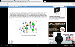
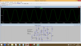
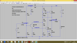
This is the JLH69 using common transistors. TIP3055 or TIP41 would make great output devices as they are flat pack. The BC small signal types are available anywhere and pretty much anything similar would be just as good. The voltages show typical values for the running circuit.
R1 sets the midpoint voltage at the output to be equal to one half the supply voltage. That could be a preset if you wanted, say a 220k adjusted for 6 volts for a 12 volt battery measured at 'Vout' point.
It will draw around 500 ma at 12 volts.
R1 sets the midpoint voltage at the output to be equal to one half the supply voltage. That could be a preset if you wanted, say a 220k adjusted for 6 volts for a 12 volt battery measured at 'Vout' point.
It will draw around 500 ma at 12 volts.
Attachments
No, I don't need the simulation file.
But I would like to optimize it for 12v using the transistors I listed earlier, and the 8ohm 5watt speaker I ordered. that would be awesome. Thanks!
But I would like to optimize it for 12v using the transistors I listed earlier, and the 8ohm 5watt speaker I ordered. that would be awesome. Thanks!
That makes sense. So I understood how you found R1, but I don't know how to figure out the other values. Same with capacitors.
Sorry this is like a teaching lesson
Sorry this is like a teaching lesson
- Status
- Not open for further replies.
- Home
- Amplifiers
- Solid State
- Diy class a 5W amplifier