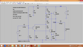
OK, here is the circuit with the component references in a more logical sequence.
C1 sets the low frequency cut off point of the basic amplifier. Using 0.47uf allows a small film type to be used. Its not critical though.
The voltage gain of the amplifier is approximately R6/R5 which is around 12.
C4 sets the lower frequency cut off of the feedback return network. It needs to be large enough not to impact on the overall response. 220 ohm and 220uf give a -3db point of just over 3Hz for that network.
Bias current is alterable by adjusting R7. Keeping it as low as practicable will maximise battery life. We are at about 0.5 amp here.
C5 is the speaker coupling cap and needs to be big for good low frequency response, so at least 2200uf.
That's about it really, it should work with any suitably rated transistors with virtually no change in performance.
Attachments
I missed describing C2. That is just a filter cap on the bias network for the first stage to keep it clean and stop any noise from the power supply entering the amplifier.
OK, good luck. Just be sure you get the transistors and caps the right way around and the two outputs are on a good heatsink. If they are metal backed transistors then be sure to insulate them properly with the correct insulating kits.
I have one last question. What is the significance of c3, and what should the voltage rating be for it?
Also, can I use a 4.7uf instead of .47 uf as a replacement for c1?
Also I don't have a 39k ohm resistor, can I use something close, like 50k? Or I might have a 33k R3.
All the other parts I have and were delivered so I'm almost ready to build
Also, can I use a 4.7uf instead of .47 uf as a replacement for c1?
Also I don't have a 39k ohm resistor, can I use something close, like 50k? Or I might have a 33k R3.
All the other parts I have and were delivered so I'm almost ready to build
C3 is called a 'bootstrap cap' and its function is to couple the output voltage to R8. Doing that means the R8 voltage 'follows' the audio and so the current through R8 is more constant. Its a refinement that was commonly used on this style of amplifier. As you are running on 12 volts a 16 volt cap would be ideal.
The 39k isn't critical at all, what is important is the voltage at the junction of R1 and R2, which of course depends on the 39k.
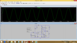
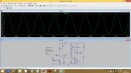
If you stray from these values then the DC voltage at the output (Vout on the diagram) will alter and that means the amp will not deliver its maximum possible output. Ideally Vout should be half the supply voltage (so 6 volts here) as that allows the output to swing equally in each direction.
This shows the effect of changing the 39k to first a 10k and then a 100k. You lose the ability to reach full output cleanly with it clipping at either top of bottom depending which way Vout strays from 6 volts. Another good option would be to make the 39k a preset (say 47k or 100k) and then you could adjust it exactly.
The 39k isn't critical at all, what is important is the voltage at the junction of R1 and R2, which of course depends on the 39k.
If you stray from these values then the DC voltage at the output (Vout on the diagram) will alter and that means the amp will not deliver its maximum possible output. Ideally Vout should be half the supply voltage (so 6 volts here) as that allows the output to swing equally in each direction.
This shows the effect of changing the 39k to first a 10k and then a 100k. You lose the ability to reach full output cleanly with it clipping at either top of bottom depending which way Vout strays from 6 volts. Another good option would be to make the 39k a preset (say 47k or 100k) and then you could adjust it exactly.
Attachments
Alright so I wired everything up, checked my connections multiple times, but it won't work.
What I noticed is that c5 which I am using 2200uf at 16v gets pretty hot pretty fast. No noise is created from the speaker except for when I flip the switch to on, that's when you here a thump just like any other speaker that you connect the power to.
Any suggestions.
For the 39k resistor, I wired 4 10k resistor together in series.
Right now I have it connected to my tablet as an input, and I've tried it with headphones and it works so it's not the tablet.
I'm wondering if it is the arrangement of the transistor pins. For q1 I am using the nte159 pnp, and with the flat side facing you, from left to right I have it as emmitter base collector. Q2 is the 2n2222 npn, emitter base collector. Q3 is nte184 npn, emitter collector base. And q4 is nte184 npn, emitter collector base.
Does that seem about right?
If an electrolytic cap. gets hot fast, you should hear alarm bells ring too! That only happens when you have it reversed or the power supply to the amplifier reversed. I don't know your power situation there but I still confuse connector polarity markings on things like wall warts - after decades of trying to work out what the tiny markings are supposed to mean.
Maybe it's that simple but check the voltage polarity across the capacitor and the power supply connections with your meter before the cap blows itself and your eardrums into the next universe.
Maybe it's that simple but check the voltage polarity across the capacitor and the power supply connections with your meter before the cap blows itself and your eardrums into the next universe.
Okay, so the first time I had it plugged in reverse. But I plugged it in the right way and it still won't work.
I've checked my connections about 7 times now haha.
The two power transistors are not even warm, like they aren't even getting turned on. I'm gonna prove around with my meter and tell you what I find
The two power transistors are not even warm, like they aren't even getting turned on. I'm gonna prove around with my meter and tell you what I find
What is the voltage and polarity measured across the capacitor with the red probe on + and black on - leads. This the acid test. If it gets hot when the connections look correct and the cap started out OK then sorry, your checks were simply wrong.
So at the base of the q1, I was reading around a constant 4v while a song is playing on my tablet.
Since this is Mooly's suggested design, I'll leave out comment on the input but if the output capacitor is OK, there should be no DC present on the speaker at all, measured with respect to ground. So, as cap. C5 is the only path, it would seem to be damaged - i.e. shorted. 🙁 Check any speaker or phones that have been used on the amplifier for continuity in that case because 12V DC will take them out fast.
Again, what specifically is the DC voltage and polarity measured across C5 leads?
Again, what specifically is the DC voltage and polarity measured across C5 leads?
Any fault-finding starts with the basics. We are working to the diagram in post #21, yes ?
Put your meter on DC volts and connect the black lead to ground.
Have the pinouts of the transistors in front of you if you are not sure. You can get data sheets from here,
Datasheet catalog for integrated circuits, diodes, triacs, and other semiconductors, view
1/ Check that the supply is correct at 12 volts as measured on Q3 collector.
2/ Check that C2 and C4 have their negative ends going to ground.
3/ Check that C3 is correctly fitted. Positive end to R7.
Now measure and record the voltages on the transistors. Copy and paste this with your readings.
Q1 Base =
Q1 Emitter =
Q1 Collector =
Q2 Base =
Q2 Emitter =
Q2 Collector =
Q3 Base =
Q3 Emitter =
Q3 Collector =
Q4 Base =
Q4 Emitter =
Q4 Collector =
Q1 Base =5.15v
Q1 Emitter =1.8mv
Q1 Collector =0v
Q2 Base =0v
Q2 Emitter =0v
Q2 Collector =12.4v
Q3 Base =12.4v
Q3 Emitter =12.0v
Q3 Collector =12.4v
Q4 Base =0v
Q4 Emitter =0v
Q4 Collector =0v
Q1 Emitter =1.8mv
Q1 Collector =0v
Q2 Base =0v
Q2 Emitter =0v
Q2 Collector =12.4v
Q3 Base =12.4v
Q3 Emitter =12.0v
Q3 Collector =12.4v
Q4 Base =0v
Q4 Emitter =0v
Q4 Collector =0v
Q1 has a problem. The 5 volts on the base is correct. The emitter voltage at 1.8 millivolts is very wrong. That can only be one of a couple of things...
Unlikely but R6 could be open circuit or there is a physical break in conductivity via R6 to Q1. Make sure R6 has 12 volts on the 'top' end that goes to Q3 emitter.
Even if Q1 were faulty, you had an NPN instead of PNP fitted or you had the leads the wrong way around it wouldn't give 1.8mv on the emitter.
One other thing to check... make sure you haven't a short from Q1 emitter to ground.
- Status
- Not open for further replies.
- Home
- Amplifiers
- Solid State
- Diy class a 5W amplifier