Back to topic, some intermodulation
fourier analysis using a somewhat brute
force method, a sum of two equal amplitude
signals at 19 and 20khz.
Pavel s SSA is added to these sims along with
Ostripper s AX2, DX amp, Leach amp, Apex ultimate,
JLH10W , Pass F5, Blame ES and ESP P3A.
fourier analysis using a somewhat brute
force method, a sum of two equal amplitude
signals at 19 and 20khz.
Pavel s SSA is added to these sims along with
Ostripper s AX2, DX amp, Leach amp, Apex ultimate,
JLH10W , Pass F5, Blame ES and ESP P3A.
Attachments
Last edited:
coils
As far as I can see, nope. (only around electrolytics)
Cheers,
E.
Nothing on this book about the case discussed here about coil wounded around the damping resistor ?.....
As far as I can see, nope. (only around electrolytics)
Cheers,
E.
Back to topic, some intermodulation
fourier analysis ...
Hi Wahab,
you are great!
I have got a feeling that last intermod simulations confirmed your first wideband fft sims...
Hi wahab,
I think the relay referred to by Doug Self was passing the current through the frame of the relay instead of through a wire as is the more common practice. The frame was an iron or steel alloy if memory serves.
As for any conductors passing through the output inductor, I suspect that you are talking about half a turn and possibly a higher resistance circuit than a shorted turn if you are considering a resistor (2R2 to 10R normally) across the coil. I'm not really sure what will happen, could be interesting. Thinking back to the designs Doug Self shows in his book, his output inductors are large diameter. He wasn't using a resistor as a coil form, that's for sure!
Hi Edmond,
You have a reply now. 🙂
Hi OS,
Really?? Wow, thank you so much!! You have just made my day! 😀
-Chris
Hi OS,
Really?? Wow, thank you so much!! You have just made my day! 😀
-Chris
You just PM me. You have many choices.
BTW , I have auditioned the mighty AX2. It is very good. Still , it falls short of the cascoded goodness of the GX.. 😀 Subtle differences in the simulations are sometimes greatly amplified in the real world.
OS
Last edited:
Back to topic, some intermodulation
fourier analysis using a somewhat brute
force method, a sum of two equal amplitude
signals at 19 and 20khz.
Pavel s SSA is added to these sims along with
Ostripper s AX2, DX amp, Leach amp, Apex ultimate,
JLH10W , Pass F5, Blame ES and ESP P3A.
Thanks for your great work, Wahab.
Would anyone comment/explain some of these results for members -like me- who hardly draw conclusions from these curves? How to read them?
Very apreciated.
Hi Wahab,
you are great!
I have got a feeling that last intermod simulations confirmed your first wideband fft sims...
Hi, Pawel
Seems that something did please you.!
Did the JLH10W perform according to your expectations?
Dont forget that it has global feedback.
I will soon complete those sims with a few more amps,
among others, Hiraga s Monster, which has also
some (moderate) GNFB.
regards
w
Thanks for your great work, Wahab.
Would anyone comment/explain some of these results for members -like me- who hardly draw conclusions from these curves? How to read them?
Very apreciated.
Hi, Bobo
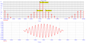
The graphic is quite simple..
Vertical logarithmic scale is graduated in volts, i.e, amplitudes.
while the linear horizontal scale stand for frequencies contents.
You can see that the tests frequencies have each 10V amplitude,
at 19 and 20KHZ, inducting a maximum output voltage of 20V when
the two signals are more or less in phase.
The intermodulation contents are sums or substraction of the
said frequencies between themselves but also with the eventual
harmonics contents created by the amp non linearities.
The first IMD product are thus 1KHZ and 39khz.
The signals at 38 and 40khz are harmonic distorsion as
first harmonics of the 19 and 20khz signals.
Those two harmonics then interact with the respective
cross frequencies, i.e 38 - 20 = 18KHZ and 40 - 19 = 21KHZ,
and create more IMD..
The reasonement can be duplicated ad eternam, as any harmonic
and IMD products modulate each others creating all the unwanted
frequencies seen on the graph.
Of course, the amplitude of those distorsion signals must be kept
as low as possible , not forgetting that there s already vast sums
of intermodulations in musical signals that are part of the music sound.
cheers,
w
Attachments
Last edited:
As far as I can see, nope. (only around electrolytics)
Cheers,
E.
Thank you Edmond.
Around electrolytics, this was in those old Dynaco s.....
cheers,
w
Thanx, Wahab.
I undersand this, though, what about the bottom of the curves that differ.
That, i do not.
I undersand this, though, what about the bottom of the curves that differ.
That, i do not.
Thanx, Wahab.
I undersand this, though, what about the bottom of the curves that differ.
That, i do not.
The bottom of the curves is of no importance, since it
varies only due to the simulator rounding infinitesimal calculus
or simply lacking some more precision, since we are in very
little values..
This can be improved graphically speaking but this would require
much longer computation time while providing no more
explicit informations..
cheers,
w
Did the JLH10W perform according to your expectations?
Dear Wahab,
I did not expected good behavior from the amp with gnfb
but JLH10W surprised me positively; it has less hf rubbish in the spectrum; one more I am afraid off is back emf...
I am going to build it as "less evil" anyway.
with great respect of your work,
Did I miss a test? Many would have looked at JLH 10W spectra and noticed a lot narrower range of harmonic distortion products than class AB examples. Looks great doesn't it? Well for the heat and power loss, you can expect some return.
It would have been good to see another class A in that first group of Ik, 10kHz THD comparisons. I was kinda expecting "Le Monstre" as you mentioned, Wahab.
Well, anyways, seeing you have a model for IMD, maybe the F5 is not too difficult?
This thread continues to be a great education, particularly with the bandwidth we don't often see here. Many thanks for your contribution.
Did I miss a test? Many would have looked at JLH 10W spectra and noticed a lot narrower range of harmonic distortion products than class AB examples. Looks great doesn't it? Well for the heat and power loss, you can expect some return.
It would have been good to see another class A in that first group of Ik, 10kHz THD comparisons. I was kinda expecting "Le Monstre" as you mentioned, Wahab.
Well, anyways, seeing you have a model for IMD, maybe the F5 is not too difficult?
This thread continues to be a great education, particularly with the bandwidth we don't often see here. Many thanks for your contribution.
Thanks, Ian.
The JLH "missing" graph should be by there...
http://www.diyaudio.com/forums/soli...dio-popular-amps-simulations.html#post2294066
...Many would have looked at JLH 10W spectra and noticed a lot narrower range of harmonic distortion products than class AB examples...
please let me explain,
this harmonics spectra has much lower frequency,
than for ABclass amp suspected for metallic annoying sound,
for me such a spectrum is a guarantee for natural, warm sound.
Wahab, I hope there is no problem if I add a simulation result of the PM-A1:
Hi , Pavel
No problem, to the contrary, this allow useful comparisons
of simulators.
Is your PM-A1 the amp described in this thread?
http://www.diyaudio.com/forums/solid-state/155628-solid-solid-state-power-amplifier.html
That s the one i did simulate in the IMD comparisons,
though i branded it PMA2...
At 19+20K, the lateral signals (F1-1 ,F2+1), at 200uV each
are 100db under the 20V peak level, which seems better than
in your 13+14K sim tests ..
Perhaps a device difference?.
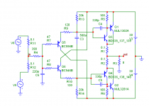
I used 2SA1837/2SC4793 driving two pairs of 2SA1943/2SC5200,
the other devices being the ones on the schematic..
Last edited:
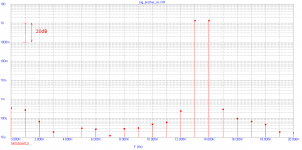
Now I would like to show the difference between simulation and measurement on the real amplifier. The amplifier is PA4 (http://www.diyaudio.com/forums/solid-state/155628-solid-solid-state-power-amplifier.html with 4 pairs of output devices, 150W/8ohm). The CCIF IMD test is 13+14kHz into 8 ohm load. Output amplitude is 56Vpeak-peak. Both plots cover same range 140dB. We can see that real amplifier has higher distortion by low order harmonics, BUT, the HF distortion seen in simulation is absent in the real amplifier. Also, We reach the noise limit. Should be said that most of simulated IMD products are deeply burried in noise. The 50Hz multiples in the real measurement are a result of ground loop by loop-back measurement.
Power transistor usual simulator models do not fit very well to reality. E.g., they do not describe minority charge carrier issues, thus do not give picture of cross-conduction etc. Cross-conduction can occur even in a class-A amplifier.
Power transistor usual simulator models do not fit very well to reality. E.g., they do not describe minority charge carrier issues, thus do not give picture of cross-conduction etc. Cross-conduction can occur even in a class-A amplifier.
Attachments

Last edited:
Is your PM-A1 the amp described in this thread?
http://www.diyaudio.com/forums/solid-state/155628-solid-solid-state-power-amplifier.html
No, the amp you speak about is PA2.
PM-A1 is attached now. It is a low output power class A power buffer.
Attachments
- Status
- Not open for further replies.
- Home
- Amplifiers
- Solid State
- Diy audio popular amps simulations