Hi mbrennwa,
I'm at a complete loss as to why you would like to do that. A scope or meter are the appropriate tools for the job. I don't use the spectrum analyser function of the 'scope to examine the signals inside circuits. On reason is that the waveform is distorted anyway, we already know this. The feedback creates a signal that is distorted in a complimentary way to partially cancel distortion created in the output stages.
-Chris
I have never had any proper training in electronics, engineering, or workshop manners. That's why I just "do stuff" when it comes to building and testing stuff in real life, and it also means I may do things differently than a trained electronics person would. Looking at signal spectra at different positions within an amp can be very useful to understand where and how signal distortion happens (yes, the feedback loops need to be disconnected first).
I think this is getting a bit off topic. Maybe start a new thread and let us know about it if you want to discuss this more.
Happy new year to everyone!
A few days ago I got one of these: Intona – Products .
I connect it between the PC running the measurement software and my USB scope TiePie HS3 Handyscope HS3 key specifications.
I can now connect the scope probe ground lead anywhere in the circuit I want and do measurements wherever I want. Works really beautiful, and should work with any USB instruments. The adapter is guaranteed to deliver 300mA at the isolated USB side, but the designer told me in practise it should be close to 500mA. Enough for most USB instruments.
This should also work well to isolate DACs.
Jan
Thanks, that's a good idea! I have one of these isolators floating around my workshop...
@mbrennwa
With the RTX6001 Audio Analyzer this does not change the situation. The analyzer is already isolated from the PC. It is supposed to be connected to earth though, through the supply cable.
How do you measure the phase?
If you make a loop back connection, you will not have a phase of 0 between the (SW) generator in the PC and the (SW) analyzer in the PC. There will be a number of delays in-between, like buffers, USB interface, DAC and ADC.
With the RTX6001 Audio Analyzer this does not change the situation. The analyzer is already isolated from the PC. It is supposed to be connected to earth though, through the supply cable.
I used REW to measure the frequency response of my unit with loopback connection. The FR result is extremely flat, but the phase is 180 degree. I've checked my cable to make sure that I didn't do the polarity wrong. Did I do something wrong? or the polarities are different between the input and output?
Paul
It is quite easy to forget about polarity in circuit design, I wonder...
How do you measure the phase?
If you make a loop back connection, you will not have a phase of 0 between the (SW) generator in the PC and the (SW) analyzer in the PC. There will be a number of delays in-between, like buffers, USB interface, DAC and ADC.
How do you measure the phase?
If you make a loop back connection, you will not have a phase of 0 between the (SW) generator in the PC and the (SW) analyzer in the PC. There will be a number of delays in-between, like buffers, USB interface, DAC and ADC.
The test signal used by REW is not a simple sine sweep. It is designed to measure not only frequency response, but also phase, impulse response, etc. Of course there will be some time delays, but they are removed by REW to make sure the results are not affected.
Paul
If you only want to check if the polarity is swapped somewhere use a test signal that looks different (modulo shift) if you swap polarity, e.g. a sawtooth.
Still waiting for my RTX6001 - is the current drawn at the RTX6001 USB port known ?Intona – Products .
The adapter is guaranteed to deliver 300mA at the isolated USB side, but the designer told me in practise it should be close to 500mA. Enough for most USB instruments.
Ulli
FYI:
I did try Intona with a PicoScope 4227 - didn't work.
4227 draws about 450 mA from the USB port.
Even with a AQVOX USB Low-Noise 5V Isolated Linear Power Supply connected to the 4227 USB port it is not working properly 😀
Using a notebook running on battery is my current solution.
cf. How to make floating or isolated measurements and break the ground loop with a USB oscilloscope?
Still on my todo list:
WaveIO has a 5V input at the output side (lower right corner).

Might be possible to modify Intona accordingly.

4227 draws about 450 mA from the USB port.
Even with a AQVOX USB Low-Noise 5V Isolated Linear Power Supply connected to the 4227 USB port it is not working properly 😀
Using a notebook running on battery is my current solution.
cf. How to make floating or isolated measurements and break the ground loop with a USB oscilloscope?
Still on my todo list:
WaveIO has a 5V input at the output side (lower right corner).
Might be possible to modify Intona accordingly.
It is quite easy to forget about polarity in circuit design, I wonder...
You are right, the phase is indeed wrong on the DAC 😱
It will be corrected in the next FW release (for the XMOS).
FYI:
I did try Intona with a PicoScope 4227 - didn't work.
4227 draws about 450 mA from the USB port.
To be honest, mine didn't work in the first try, until I changed the USB cable for one that has decent supply cabling. USB cables vary a lot in wire size which is no issue for the data connection but sometimes makes a difference on the power side. Some of these wires are minuscule, especially in the thick cables ;-)
Jan
You are right, the phase is indeed wrong on the DAC 😱
It will be corrected in the next FW release (for the XMOS).
Thank you Jens.
Cheers,
Paul
You are right, the phase is indeed wrong on the DAC 😱
It will be corrected in the next FW release (for the XMOS).
Is the phase wrong in terms of time offset or in terms of polarity?
Still on my todo list:
WaveIO has a 5V input at the output side (lower right corner).
Let me know if you need a WaveIO. I have a brand new board that I don't need.
Is the phase wrong in terms of time offset or in terms of polarity?
In terms of polarity. When working with sine waves it is not a big issue 🙂
You are right, the phase is indeed wrong on the DAC 😱
It will be corrected in the next FW release (for the XMOS).
A firmware change?
And there will be a software utility that allows us to perform the firmware upgrade I suppose?
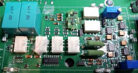
@ JensH: On one of the pics of nyt (attached cropped) there are white lines, on the pcb, forming a cuboid and some ground (?) clips along these. Are these lines show the traces of a provisional of some kind of metal shield over the inputs circuitry which are not included in GB units?
Happy New Year to All!
Happy New Year to All!
Attachments
Last edited:
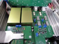
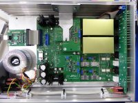
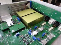
They are for input stage shielding. I've tried to install two SPTE shielding boxes, but the crosstalk is not reduced, which confirms what Jens has said. In addition, the crosstalk level does not change by switching to different input gains/attenuations. Therefore I think that it might be the crosstalk inside the ADC. Since these shields make no difference, I've removed them from my unit.
However, the measurements are usually done with single channel. Therefore I guess crosstalks should not be an issue for most cases.
However, the measurements are usually done with single channel. Therefore I guess crosstalks should not be an issue for most cases.
Attachments
Last edited:
@Ghianni
Yes, the clips were included to have the option of mounting shields over the input stages.
As described earlier, it was decided not to mount any shields.
@PaulBC
Very nice shields you have made!
As someone pointed out earlier, there is some crosstalk, primarily from the right generator output to the left input, due to the proximity. The shields will reduce this crosstalk. The ADC will cause some crosstalk between the input channels, which the shields will not change.
Some components in the input stages become relatively hot, so closed shields like the ones you have made are not recommended and will void the warranty.
Hi Jen
one question on Single ended input - is it worthwhile building an electronic converter for RTX or cable solution ( earlier reference on this thread for suitable converter cable) is more than adequate ? I Was wondering whether electronic converter ( similar to AP sys series analyzers) as that can be using long length balanced cable from DUT will be better than cable? If so can you please suggest suitable schematics. Most of my use will be single ended connections from DUT.
one question on Single ended input - is it worthwhile building an electronic converter for RTX or cable solution ( earlier reference on this thread for suitable converter cable) is more than adequate ? I Was wondering whether electronic converter ( similar to AP sys series analyzers) as that can be using long length balanced cable from DUT will be better than cable? If so can you please suggest suitable schematics. Most of my use will be single ended connections from DUT.
Last edited:
- Home
- Design & Build
- Equipment & Tools
- DIY Audio Analyzer with AK5397/AK5394A and AK4490