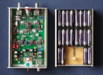
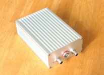
Here's mine:
An externally hosted image should be here but it was not working when we last tested it.
Jack,
I'm thinking of making one myself. Did you use the +-7.5 volts to run the opamps as well? The ap note isn't clear on this point.
Thanks
Ken
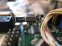
One more thing, I know Frex is busy but perhaps this will help others. The Tent clock doesn't really fit very well. You need to move the 10uF capacitor off-center of its pads, and tilt the clock to avoid an inductor and capacitor. See pictures.
Regardless, the clock will make contact with the metal casing of the input transformer. I'm hoping this is okay, as there is no other way around it that i can see. Anyone know for sure if this is okay?
Regardless, the clock will make contact with the metal casing of the input transformer. I'm hoping this is okay, as there is no other way around it that i can see. Anyone know for sure if this is okay?
Attachments
Jack,
I'm thinking of making one myself. Did you use the +-7.5 volts to run the opamps as well? The ap note isn't clear on this point.
Thanks
Ken
I used "D" cells, a pack of 5 on each side.
In my case, it was very important to shield the oscillator, so both batteries and the PCB were housed in a big Danish cookie tin.
I used "D" cells, a pack of 5 on each side.
In my case, it was very important to shield the oscillator, so both batteries and the PCB were housed in a big Danish cookie tin.
Thanks Jack. I get the strong sense that you love Danish cookies 😀 .
Just finished my oscillator.
Battery powered, Lemo2B for balanced output. Rest is standard.
At the moment -130dB H2 limited by noise floor of spectrum analyser.
Shall measure again in 2 weeks when I have access to an AP.
Thanks for the PCB work,
Patrick
Battery powered, Lemo2B for balanced output. Rest is standard.
At the moment -130dB H2 limited by noise floor of spectrum analyser.
Shall measure again in 2 weeks when I have access to an AP.
Thanks for the PCB work,
Patrick
Attachments
Patrick, looks good! Do you anticipate any problems due to the two halves of the battery pack not discharging at equal rates? Or is the on board regulator enough to deal with this?
a) The oscillator has pure AC output. My test with lab supply suggested that consumption was equal for positive and negative rail.
b) 20 AAA alkaline batteries cost 3 Euros and will last me for hours. So even if they are discharged unevenly, just replace new.
c) I don't think I'll be switching them on very often.
Too many advantages with batteries IMHO.
Patrick
b) 20 AAA alkaline batteries cost 3 Euros and will last me for hours. So even if they are discharged unevenly, just replace new.
c) I don't think I'll be switching them on very often.
Too many advantages with batteries IMHO.
Patrick
Hi Frex
Impressive pcb work, fine.
Maybe you are looking for something readymade, and possible unbeatable, take a look at TI's PCM4222EVM ( US $ 149,-- +shipping ).
You just need a dual 15V and single 5V powersupply.
Here a FFT; source Krohn-Hite 4400A, both units SLA battery driven, PC interface RME-PAD via AES/EBU.
Does your KH4400A have any mods since most people quote .0001 - .0003% distortion for that unit?
Well, let's remember:
1. SLA driven, to get rid of 50Hz artefacts and cross IM.
2. Calibration of the AGC fet section according to the service manual,
available at Jan Dupont's great site.
3. Replacement of the output level pot, got a 10 turn Bourns there.
Getting the 4th zero in THD was the "sweet spot" in connecting the KH4400A to the TI ADC eval board. So, even a slight change of the volume level increases THD to 0.000x. At least this is THD, not THD+N; did 10^6 FFT points to minimize the noise part.
BR
Gary G.
Hello all,
As i had already say in my previous post, the 10M resistor can be any tolerance (1-5%).It's not critical. Just use metal film resistor, no carbon type.
Tolerance noted in the BOM is a mistake. Sorry.
AR2, i'm glad you finally got your PCB !
Now you can start the job 🙂
Valeriano have finish his wiring and seem to have a working ADC (correct me if i'm wrong).He has report me a mistake concerning the two resistor R49 and R50.
(divider of the LT1963 voltage regulator).
For proper work you should solder as below :
R49=750 Ohms (but no 249)
R50=249 Ohms (but no 750)
I will notify that on the wiki page for all users.
AR2, i already have built two audio DAC , they just has not been described on the forum yet.
Just two pictures for you.
An externally hosted image should be here but it was not working when we last tested it.
An externally hosted image should be here but it was not working when we last tested it.
Regards.
Frex
Hello Frex,
Where can I read more about this project? This DAC looks very versatile! How did you implement the USB connectivity?
Thanks,
Mike
Hello,
Unfortunatly, the web site that i had started to design some month ago is not yet ready and i don't have described this project on DIYaudio.
Probably because many DAC design has already designed and described on DIYaudio !
But yes, this DAC is very versatile.
The USB input use the very common PCM2906 that allow only 16bit/44-48kHz operation, but the internal
DACs are dual PCM1792A in mono mode with fully differential operation.
Optical and coax input can handle 24bits/192kHz.
The DAC can be controlled (digital volume and mute) with any RC5 compatible remote control.
If you are interested by the project, i have some bare PCBs of this design that i can sale. Of course, all design files will be provided.
If many DIYers ask me, i could also strat a dedicated thread.
HERE, you can read the full schematics.
Regards.
The PCB view :
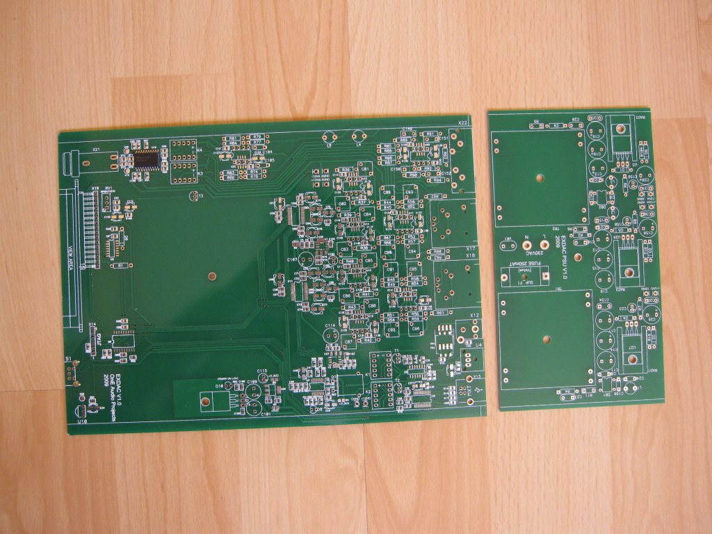
The internal view:
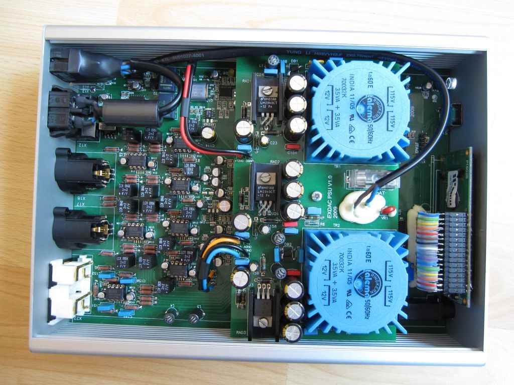
FRex
Unfortunatly, the web site that i had started to design some month ago is not yet ready and i don't have described this project on DIYaudio.
Probably because many DAC design has already designed and described on DIYaudio !
But yes, this DAC is very versatile.
The USB input use the very common PCM2906 that allow only 16bit/44-48kHz operation, but the internal
DACs are dual PCM1792A in mono mode with fully differential operation.
Optical and coax input can handle 24bits/192kHz.
The DAC can be controlled (digital volume and mute) with any RC5 compatible remote control.
If you are interested by the project, i have some bare PCBs of this design that i can sale. Of course, all design files will be provided.
If many DIYers ask me, i could also strat a dedicated thread.
HERE, you can read the full schematics.
Regards.
The PCB view :
The internal view:

FRex
Hi Frex ,
Dropped a mail to contact@oneaudio.com , if it is not up , please drop me a mail to dasgupta.s@outlook.com
Suranjan
Dropped a mail to contact@oneaudio.com , if it is not up , please drop me a mail to dasgupta.s@outlook.com
Suranjan
Uh... why is this called an A to D project when it is about a D to A?
I am looking for the lowest THD ADC on the planet.
Thx-RNM
I am looking for the lowest THD ADC on the planet.
Thx-RNM
Hello RNM,
Maybe you could read the thread at it's start, will help you to understand the title. 🙂
This page speak about another of my projects that is effectively an DAC.
RNM, you seem to search the Grail.
To my experience and despite it's oldness the AK5394 seem to be again the best audio ADC with lowest THD and noise floor.
A newer ADC from ESS (ES9102) seem interesting on the paper, but despite it's announcement from many years now, i don't have read a serious review of it's real world specs and measured THD/noise performance.. Only some promises...
I have also burn many time and effort to find a good THD measuring system, and the better ADC i've find is the LTC2377-20 from Linear Technology. The specs say -125dB !But no EVM available.
The best compromise (to my opinion) is the LTC2378-18 or LTC2389-18.
The first is a 18 bits 1Msps ADC with THD of -124dB@2kHz, and the second is a 18bits 2.5Msps ADC with THD -116dB@2kHz.
Each of this ADC have their EVM available for sale at about 450 USD.
It's not a audio ADC, but i think these EVM could be a very very good piece of gear !
The analyzing bandwidth is much wider that any delta/sigma ADC, that can give interesting informations in spurious noise of audio equipment (and others).
Maybe all of that will help you a little in you quest ! 🙂
Regards.
Frex
the AD PulSAR parts hold up much better in the datasheet thd vs frequency plots compared to the LTC ADC
Hello Jcx,
You answer is a little short, don't you think ?
Comparing ADC specs is no so easy because many parameters must be carefully read.
Could you start to say what ADC are you comparing exactly ?
FRex
You answer is a little short, don't you think ?
Comparing ADC specs is no so easy because many parameters must be carefully read.
Could you start to say what ADC are you comparing exactly ?
FRex
This all good stuff. yes, the Grail. I can now accurately measure below the ADC levels so now want to have the best ADC I or you can find as a basic additional tool.
The fast ADC will be very insightful during transient analysis.... finding issues that nice easy sine waves do not invoke in a product.
What can I beg, buy, borrow or steal that are available in some finished or simi-finished form? All input welcome.
Thx RNMarsh
The fast ADC will be very insightful during transient analysis.... finding issues that nice easy sine waves do not invoke in a product.
What can I beg, buy, borrow or steal that are available in some finished or simi-finished form? All input welcome.
Thx RNMarsh
Bonjour Frex!
Tu tombes en plein dans le mille avec moi pour ce genre de projet!
Je suis du Québec! 🙂
And now, I guess we are better to continue in english! 😉
This is the kind of projects that rekindle my interest in DIY. Let me read all the thread and I will come back later.
My current need is a 8 chanels of ADC to ADAT for a mic preamp I am building.
Thanks for this!
Luc
- Home
- Design & Build
- Equipment & Tools
- DIY Analog-to-Digital Converter project.Audio measurements tool

