great on the board
I would have to be really in a jam to purchase that resistor,lol.
Have to keep that piece of test equipment in a safe,lol.😀🙂
I'll watch the mailbox,,,,,,,,,,,
I would have to be really in a jam to purchase that resistor,lol.
Have to keep that piece of test equipment in a safe,lol.😀🙂
I'll watch the mailbox,,,,,,,,,,,
For the 10M resistor,the precision in the BOM is a mistake.
You can use 1% or 5% value without any problem.
Just use metal film type, no carbon(high noise).
Frex
Hello all,
As i had already say in my previous post, the 10M resistor can be any tolerance (1-5%).It's not critical. Just use metal film resistor, no carbon type.
Tolerance noted in the BOM is a mistake. Sorry.
AR2, i'm glad you finally got your PCB !
Now you can start the job 🙂
Valeriano have finish his wiring and seem to have a working ADC (correct me if i'm wrong).He has report me a mistake concerning the two resistor R49 and R50.
(divider of the LT1963 voltage regulator).
For proper work you should solder as below :
R49=750 Ohms (but no 249)
R50=249 Ohms (but no 750)
I will notify that on the wiki page for all users.
AR2, i already have built two audio DAC , they just has not been described on the forum yet.
Just two pictures for you.
Regards.
Frex
As i had already say in my previous post, the 10M resistor can be any tolerance (1-5%).It's not critical. Just use metal film resistor, no carbon type.
Tolerance noted in the BOM is a mistake. Sorry.
AR2, i'm glad you finally got your PCB !
Now you can start the job 🙂
Valeriano have finish his wiring and seem to have a working ADC (correct me if i'm wrong).He has report me a mistake concerning the two resistor R49 and R50.
(divider of the LT1963 voltage regulator).
For proper work you should solder as below :
R49=750 Ohms (but no 249)
R50=249 Ohms (but no 750)
I will notify that on the wiki page for all users.
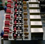
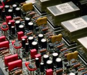
AR2, i already have built two audio DAC , they just has not been described on the forum yet.
Just two pictures for you.
An externally hosted image should be here but it was not working when we last tested it.
An externally hosted image should be here but it was not working when we last tested it.
Regards.
Frex
Hello all,
Now you can start the job 🙂
i will, I certainly will, once I finish this project...
AR2, i already have built two audio DAC , they just has not been described on the forum yet.
Just two pictures for you.
Analog ballanced buffered Tx output for 6 of your DACs, he he


Attachments
Last edited:
Hi Frex
Impressive pcb work, fine.
Maybe you are looking for something readymade, and possible unbeatable, take a look at TI's PCM4222EVM ( US $ 149,-- +shipping ).
You just need a dual 15V and single 5V powersupply.
Here a FFT; source Krohn-Hite 4400A, both units SLA battery driven, PC interface RME-PAD via AES/EBU.
If you need speed -- take a look at the ADS1675 from TI.
ok, a few more questions.
For R1, R14, R15, R28 would 619 or 649 .1% be appropriate? The lead time on 634 .1% is a bit long.
Will Mouser 571-5-1634513-1 fit for the right angle BNC connectors? I'm assuming 50 ohm impedance?
That 5 pin DIN connector you use looks really nice. I'm assuming it's an Amphenol Tuchel, but I cannot find it. Could I get a part number for that as well?
Thanks!
hi frex,
Could you make a pic of the insides or of the board and make them full screen size?
This is my 1st venture into sm devices and it will help me id parts,and what they look like,
Thanks !!!!!!😀
Could you make a pic of the insides or of the board and make them full screen size?
This is my 1st venture into sm devices and it will help me id parts,and what they look like,
Thanks !!!!!!😀
Hello luvdunhill,
R1, R14, R15 and R28 values are not critical. You can use 619 or 649 without problem.
You don't need to use 0.1% type; 1% are OK here. I will correct this too in BOM.
BNC connectors can be 50 or 75 Ohms type.We use it in low frequency range, so typical impedance
ie not a concern.
The Mouser part " 571-5-1634513-1" is ok for BNC PCB connector.
The 5 pins DIN connector is a Lumber ref KFV50/60, RS part n°167-3659 or Farnell 119-3067.
noSmoking, You talk about AA5381 PCB ?
Ragards.
Frex.
yes FREX
A full size thats maybe a little better to read.
I found the others in the eailer posts they fuzz out when I make them bigger,
Thanks Alot!😀
A full size thats maybe a little better to read.
I found the others in the eailer posts they fuzz out when I make them bigger,
Thanks Alot!😀
Hello luvdunhill
Thank you! I'm squared away on this one.
Once you have a second, could you give me a few pointers on your oscillator project? See here:
http://www.diyaudio.com/forums/grou...-sine-oscillator-group-buy-5.html#post2443322
ok, one more question. Which of the following will work for the inverter U2:
TI SN74AHCT1G14DBVT
On MC74HC1G14DTT1G
I thought I had the right part, but just realized the one I had won't fit :/
TI SN74AHCT1G14DBVT
On MC74HC1G14DTT1G
I thought I had the right part, but just realized the one I had won't fit :/
Hello,
It's a standard HCMOS single inverter gate in SOT23-5 SMD package.
The TI ref SN74AHCT1G14DBVT is not compatible because it's AHCT gate, it can’t work with 3.3V supply (4.5 to 5.5V).
The ON semi ref MC74HC1G14DTT1G seem to be ok.
Many others manufacturers are same gate.
Regards and good luck. 😉
Frex.
Hello,
It's a standard HCMOS single inverter gate in SOT23-5 SMD package.
The TI ref SN74AHCT1G14DBVT is not compatible because it's AHCT gate, it can’t work with 3.3V supply (4.5 to 5.5V).
The ON semi ref MC74HC1G14DTT1G seem to be ok.
Many others manufacturers are same gate.
Regards and good luck. 😉
Frex.
Thank you! I'll try the On part.
Also, perhaps Mouser 647-RR71A471MDN1 is a better cap than the specified Sanyo SP cap. Just noticed it's a "new technology" at Mouser.
thank you for the advise in the documentation for W3 and W4. I will be populating the low noise voltage source.
For W1 and W2 it looks like I need to close W1 and W2, since I will only be providing the +-15VDC input. Is this correct?
For W1 and W2 it looks like I need to close W1 and W2, since I will only be providing the +-15VDC input. Is this correct?
The two jumpers W1 and W2 allow to check regulated voltages before connected them to all IC. Once you have check this, you can close them.
Regards.
Frex
Regards.
Frex
hi
do you still have pcb's for this project??? all chip's and others elements are soldered or it s a kit? i could be interest to order 10 pcs....je parle francais aussi..
merci
do you still have pcb's for this project??? all chip's and others elements are soldered or it s a kit? i could be interest to order 10 pcs....je parle francais aussi..
merci
The 5 pins DIN connector is a Lumber ref KFV50/60, RS part n°167-3659 or Farnell 119-3067.
Do these connectors need a keyed opening, like on this datasheet? I notice that Frex's documentation just has a simple round hole.
http://www.farnell.com/datasheets/44049.pdf
I don't have any in my hand yet, but wanted to work on the panels.
- Home
- Design & Build
- Equipment & Tools
- DIY Analog-to-Digital Converter project.Audio measurements tool