“future me” could learn to trust “past me” a little bit.
In my case I trust past me of say 5 years ago more than I do past me of 15 years ago.
Also, it’s a good idea to take build notes as you go, so there’s something to look back on. But do I actually do that? Maybe, sometimes.
In my case I trust past me of say 5 years ago more than I do past me of 15 years ago.
Also, it’s a good idea to take build notes as you go, so there’s something to look back on. But do I actually do that? Maybe, sometimes.
Last edited:
^ Love it! 
My lack of memory requires me to keep files of all the build notes etc. I used for each thing. If I forget my filing system, then I'm summarily screwed.
My lack of memory requires me to keep files of all the build notes etc. I used for each thing. If I forget my filing system, then I'm summarily screwed.
I am right there with you. It is a challenge (for me at least), and I never like to assume anyone's level of knowledge.Thanks, everyone, for your replies. Basically I was wondering if I needed to insulate the transistors, because on some amps you do, including the Amp Camp Amp. The build guide for the ACA mini doesn't even mention this; it would help if it said "You do not need to insulate the transistors". Yes, I can look at the circuit diagram and see that the heatsinks are themselves connected to ground, and that since power comes from a wall-wart, there is no possibility for a ground loop, but that's getting past beginner-level mojo and makes me wonder if I didn't forget something else which is also just as obvious to an expert ("can't you just look at the circuit and see?") but not to me.
I don't know that it has much to do with ground loops per se, but I might be way off base.
I may have this totally flipped or just plain wrong ... but ... you've noticed and pointed out a few key aspects of the circuit(s). There's a little more to the story as I see it.
In this circuit and with this board layout... the drains for Q3 and Q4 are connected to each other via their center pins through trace X on layer 1 of the board. That's one piece.
In this circuit and with this board layout... the drains for Q3 and Q4 are also connected to other parts of the circuit. Those connections occur through the 'back pad' of Q3 and Q4 through the heatsink and via trace Y on layer 2 of the board and onto their respective destinations.
So... if you remove the electrical connection of the drain(s) to the heatsink, you remove the electrical connection from the drain(s) to the other parts of the circuit.
Now, I don't know the ramifications / how that would manifest itself. I've no clue. However, I am pretty sure it's not how it was designed. Nelson was very kind to tell people his recommended 'work around' if people wanted to isolate the sinks from the devices, perhaps to protect themselves from their future selves or other very good reasons. The specific person that has that very good reason is also (IMHO) an expert that knows how to deal with such things and probably would not need to ask how to do so.
For a FW amplifier (take the Aleph J for instance) ... examining the schematic and observing that the heatsinks will be electrically connected to mains earth via a very low impedance connection in a great number of situations, it would be ill-advised to have the drains of the MOSFETs connected to each other and to mains earth ... bad things might happen. So, it's necessary to electrically isolate them from the heatsinks (mains earth) and from each other.
For the ACA; you're using two "same sex" devices vs. how the ACA Mini works its magic. So, all bets are off there too. Same idea, but different implementation.
I may have it all wrong... but even if I do... others will help me learn. Either way, I hope my overall point is correct... which took me long enough to get around to. Your observations are spot on, but there's more to the story. Each circuit is different. The designers' choices for how to layout the circuit onto PCBs etc. plays a big role also. It can be insanely confusing.
Mark is spot on, and his reasons are very sound. However, until I'm an expert... and I'm not one... clearly... I try to do it just like (I think) the designer intended.
Fair. Which guide were you using?An explicit call-out in the docs/build guide would be helpful.
Awesome!Thankfully all of your answers above have given me the clarity I needed. As always, appreciate this forum.
Let us know what you think when it's all done.
Last edited:
If the mosfets are isolated from the heatsinks, the mosfet drains are still connected to the circuit. The middle pin of each mosfet, which is the drain, is connected to a top layer trace on the circuit board. Note that the heatsinks are also connected to the same trace so that even if the mosfets are isolated from the heatsinks, if you touch the circuit ground and the heatsink you will be shocked.

Ben, thanks so much for chiming in. I know it's a pain in the rump.
I fully admit that I may have ooked it up big time, but I really tried to think this one through and measure on real boards.
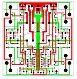
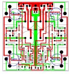
Attached is the board layout from the article. Can you point out where the trace that connects the drains through the center pin (red) connects to the trace that connects the drains to the rest of the circuit through the pad for the heatsink (green).
I also used a meter set to continuity on real boards (unpopulated) to measure between the center pins and what I thought were relevant points on the boards....
I missed something.... grrrrrrr.
Oh well, this is how I learn.
Apologies to all.
I fully admit that I may have ooked it up big time, but I really tried to think this one through and measure on real boards.
Attached is the board layout from the article. Can you point out where the trace that connects the drains through the center pin (red) connects to the trace that connects the drains to the rest of the circuit through the pad for the heatsink (green).
I also used a meter set to continuity on real boards (unpopulated) to measure between the center pins and what I thought were relevant points on the boards....
I missed something.... grrrrrrr.
Oh well, this is how I learn.
Apologies to all.
Attachments
Last edited:

Patrick, The top trace shows the mosfet drains connected to the heatsinks. As Nelson said, there is a bottom trace that also connects the drains together and to C2, but that is not visible as it is directly under the top trace. That can be seen teeing off toward C2.
Sometimes it needs some reading between the lines, or in this case reading under the lines.
Sometimes it needs some reading between the lines, or in this case reading under the lines.
Attachments
^ Thank you Nelson!
Between you and Ben, I might learn something.
I thought I may be missing something with the picture of the layout because it doesn't clearly depict all the bottom traces, and there is no separate picture showing the underside.
I thought it may be that I completely misunderstood the heatsink... well, I was right!
I have completely wasted everyone's time. I did not have the heatsinks in hand, and the pads for the two pins are isolated...
Well, if anything ... I learned something.
Once again, I apologize that my learning came at the waste of time for everyone else.
Edited to add - Ben also posted in between. Thank you again, Ben!!!! This community is amazing.


No waste of time at all, instead a learning opportunity for everybody.
😎
😎
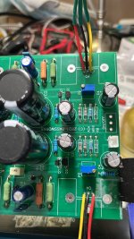
A quick help on my aca mini which I have put inside a cabinet. I have removed the toggle switch from the pcb and wanted to connect to the front panel push type switch. How do I connect the 2 pin switch?
Attachments

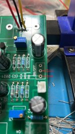
I think you need an on-on switch. I tried to connect a push button but it was on-off and the power supply would go into limp mode. I gave up for now.
The 3 pin toggle switch is wired to be on in one position and off in the other position. The third pin is not connected. It is used as an on-off switch and behaves as a 2 pin switch. A 2 pin push button on-off switch would behave exactly the same electrically. Just make sure that it is not a momentary on switch.
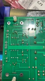
Thanks @Ben Mah i see that the other 3rd pin goes to the ground pad. So I will connect to the pads that you suggested and I am not using a momentary switch just a push type and holds its position till you push it once again to disengage.Connect to the two pads that have traces running to them:
I did not see the pad connection in your photos. Hold off on the switch while I have another look. This time I will also look at Nelson's article.
Edit:
I just looked at Nelson's article and the pcb artwork in his article looks different from your pictures. Looking at your pictures I only see two of the switch pads connected to traces. The third pad does not appear to be connected to anything.
Edit2:
I looked at your pictures again and I realized that I had the orientation of the back side of the board wrong in my mind. So hold off while I get my head and brain around the orientation of the components and traces.
Edit3:
It looks like what I showed in post #2,234 is correct.
Last edited:
I think you need an on-on switch. I tried to connect a push button but it was on-off and the power supply would go into limp mode. I gave up for now.
If your switch is a on-off switch (push for on, push again for off), perhaps you connected it to the wrong pads, shorting out the power supply.
I just looked at the schematic and the 3 pin toggle switch does not turn off V+. What it does is it disconnects the voltage to the JFET gates, and grounds that connection point. With a 2 pin switch, the voltage will disconnect the voltage to the JFET gates, but will not ground that connection. I am not sure whether the ground connection is necessary or not. This calls for expert advice from Nelson.
I can see that if it is not grounded, C5 may take a long time to discharge so the amp will run for a long time after the switch is turned off.
I can see that if it is not grounded, C5 may take a long time to discharge so the amp will run for a long time after the switch is turned off.
Last edited:
- Home
- Amplifiers
- Pass Labs
- DIY ACA mini