https://www.amazon.com/Uni-Ball-Jet...9Y2xpY2tSZWRpcmVjdCZkb05vdExvZ0NsaWNrPXRydWU=
This pen is the smoothest pen I have ever used. Not sure if the smoothest feel will convert it into enhancing the performance of a tonearm. Your experiment makes me think about my ongoing build TP arm.
This pen is the smoothest pen I have ever used. Not sure if the smoothest feel will convert it into enhancing the performance of a tonearm. Your experiment makes me think about my ongoing build TP arm.
Pilot made some pen refills in which a tungsten carbide ball was supported within a metal tube that was crimped in three places behind the ball, which should result in very low friction.
JP2005119281A - Pipe-type ballpoint pen chip and its manufacturing method
- Google Patents
hth, jonathan
Thanks Jonathan, I'll look into these sounds exactly what I need.
Found them Pilot Precise V7 I'll buy some when I'm in town next week. Thanks
Last edited:
Pilot Hi-Tec-C pen review - The Greatest Pen Ever Made - YouTube
How to Refill the Pilot Hi-Tecpoint, VPen (Precise or Varsity) - YouTube
Pilot Hi-Tecpoint V10 Grip - V5 vs V7 vs V10 Pens Compared - YouTube
It appears that the Hi-Tec-C, Hi-Tecpoint, and Precise (retractable tip) all use the three-point crimped ball system. But since Pilot uses different sub-branding or product names, depending on the market, there could very well be other products that are of this type.
rgds, jonathan
Thanks again, the plan is to try a few different pen tips to see which works best for both sensitivity and rigidity.
The Bic point uses oil based ink so the ball rotates in the tip seat not in the setscrew. This negates the need to radius and polish the setscrew.
I'll post the results once I have tested different tips.
The Bic point uses oil based ink so the ball rotates in the tip seat not in the setscrew. This negates the need to radius and polish the setscrew.
I'll post the results once I have tested different tips.
Here is a video I did at the same time as the sensitivity using the Bic pivots. The ONLY difference is the COG of the CW. In the first section there is a carbide end mill on the underside of the CW which is removed and the arm re-balanced.
With the COG in the center of the arm wand it stays anywhere it's put. VTF will be the only restoring force, there is no unwanted movement. Static VTF variation is less than 1 count (0.01g) with a height variation of 8mm.
The seesawing in the first section is IMO a bad thing, any warp induced movement however small will excite the arm into this seesaw effect. The result will be modulation of the audio signal at the seesaw frequency.
DIY Tonearm stability test -2 - YouTube
I have never thought this. So, your experiments imply that a lighter counterweight but far away from the center of gravity is better than a heavier counterweight but near the center of gravity due to the latter causes of seesawing. Is it possible that your bearing is too tight?
When I designed my air-bearing arms, I purposely designed the counterweight away from the center of gravity. The reason to do that was to reduce the total mass. But later on, I found that doing so didn't make too much of a difference in mass and it makes no difference for air-bearing since air-bearing can take heavy arm.
When I designed my air-bearing arms, I purposely designed the counterweight away from the center of gravity. The reason to do that was to reduce the total mass. But later on, I found that doing so didn't make too much of a difference in mass and it makes no difference for air-bearing since air-bearing can take heavy arm.
Last edited:
BELOW or AT center of gravity
You are missing the point. It is about the mass of the counterweight being BELOW instead of AT the center of gravity that created the seesaw effect of oscillation. It is the vertical placement of the mass not the fore and aft of the counterweight. The reason he moved the counterweight further so the arm is balanced to zero so he can demonstrate the vertical movement.
(Most unipivot designs necessitated the use of low slung counterweight in order to stabilize the arm and lessen azimuth rocking but at the same time created this seesaw effect of oscillation on the vertical movement. The Graham Phantom is an exception and is neutral balance but is aided by the use of magnetic stabilizing, for example.)
You probably missed visually the attached metal piece below the counterweight.

So, your experiments imply that a lighter counterweight but far away from the center of gravity is better than a heavier counterweight but near the center of gravity due to the latter causes of seesawing.
You are missing the point. It is about the mass of the counterweight being BELOW instead of AT the center of gravity that created the seesaw effect of oscillation. It is the vertical placement of the mass not the fore and aft of the counterweight. The reason he moved the counterweight further so the arm is balanced to zero so he can demonstrate the vertical movement.
(Most unipivot designs necessitated the use of low slung counterweight in order to stabilize the arm and lessen azimuth rocking but at the same time created this seesaw effect of oscillation on the vertical movement. The Graham Phantom is an exception and is neutral balance but is aided by the use of magnetic stabilizing, for example.)
You probably missed visually the attached metal piece below the counterweight.
The seesawing in the first section is IMO a bad thing, any warp induced movement however small will excite the arm into this seesaw effect.
No, it won't. The seesaw effect is the natural frequency of the pendulum created by the underslung CWT. When the arm is playing a record, the stylus is in contact with the record surface and it is the compliance of the cantilever suspension acting against the effective mass at the business end of the arm that determines the resonance frequency. The seesaw effect will not affect the resonance frequency but it will cause a variation in VTF with warp height.
You are overthinking this. Get some sleep
Ray K
DD
I saw the end mill. If the purpose of the test is as you said, the test should be done as follow.
The counterweight should be left on the rear of the arm as it while VTF should be 1.8 g or so. Then, take the counterweight off the arm and use a tape or a thread to hang the same counterweight under the arm. The counterweight is not on the same plane as the arm, but it is in the same position vertically as the counterweight on the arm. Therefore, such a test will illustrate what exactly as you said.
Furthermore, I am not sure about his view on seesaw frequency either.
Last edited:
I tried the same tests on my air-bearing arm since I don’t have pivot arm. Please see the following videos.
No seesaw. You can see the counterweight is on the arm.
IMG 2844 - YouTube
With seesaw. The same counterweight is attached to a piece tape and hang on the same position as it was on the arm.
IMG 2845 - YouTube
My tests have the same results as warrjon's . However, I really can’t say which is good and which is bad. Let’s assume there is warp. The counterweight that is under the arm may introduce a natural tendency to force the arm down. The counterweight that is on the same plane as the arm may lack the natural tendency to force the arm down, but it may have the tendency to keep the arm stable. Which is better? I don’t know. A correct VTF will force the arm down anyhow. Damping and correct VTF are the keys to fight warp. So, it probably makes no difference. If there is a difference, we may have to look at it from different perspectives.
balance systems
Whichever balance system is beneficial/important or not, I leave it up to the user to decide.
Bob Graham used to have a whitepaper on balance systems on his website about his Phantom tonearm but it's gone now. I found a pdf version of it. Below is the part of the content quoted from it for anyone's perusal. While it's about a unipivot design but much of it can be applied to other designs.
We've addressed the all-important (and often ignored) area of dynamic balance.
• Tonearms should have as little inertia as possible. The Phantom, in spite of its robust appearance, has been designed with a very low moment of inertia, so that the majority of phono cartridges can be used with ease and maximum performance.
• The most desirable system for tonearms is Neutral Balance. With this system, the pivot point and the Centre of Gravity of the moving system are in the same plane. When the arm is raised or lowered, there is no opposing force trying to return the arm to a rest position; the pivoting system doesn't really know or care if the stylus is at the record surface level or a half-inch above or below it; as a result, there is no opposing force to the arm as it is traversing record deflection during play. The only downward tracking force is that of the adjustable counterweight, which remains constant.
See “A BRIEF DESCRIPTION OF BALANCE THEORY” hereafter
_______________________________________
A BRIEF DESCRIPTION OF BALANCE THEORY
There are basically three types of static balance systems, Stable, Unstable and Neutral.
Stable balance, normally seen in laboratory scales, occurs when the CG (center of gravity) of the moving system is placed BELOW the pivot point. When this type of system is displaced from its preferred rest position, it will generate an immediate and opposing force which tries to return to that same position.
Unstable Balance, completely undesirable for any tonearm application, is when the CG is placed ABOVE the pivot point. A moving system with unstable balance will not have any stable position, and will exhibit reduced force as it's lifted.
Previously, all true unipivots - that is, those with a single contact point for the bearing and NO secondary stabilizing surfaces, bearings, etc. - required the use of side weights or a significantly lowered counterweight in order to provide stability. (And even those with a secondary stabilizing guide generally require a displaced CG in order to provide constant contact with the stabilizer guide piece).The drawback to both these conditions is that this design becomes a Stable Balance system, which is normally used, as mentioned, in laboratory scales for precision weight measurements. But laboratory scales have very different requirements than a tonearm. If Stable Balance is applied to tonearms, the arm will have a preferred rest position and always tries to return to this point; any change in tonearm height, as in tracking warped records, causes an immediate and equally opposing force that tries to push the arm back to its rest position. The higher the warp, the more counter-force is applied.
You can see that this force would work against the cantilever, deflecting it during warps and causing the magnetic system to be displaced. This, in turn, will certainly affect the reproduced sound, with diminished performance in all areas, including soundstage compression, loss of detail and dimensionality, not to mention record wear. This is why most tonearms must have their tracking force measured at the record surface level; any height change during the measurement will cause an incorrect reading.
A tonearm with Stable Balance can be identified by measuring the tracking force at the record surface level and again at a raised position above the record. If the tracking force INCREASES at the higher position, the arm has Stable Balance. Our own previous designs - the best we could make at that time - also had this limitation due to the use of side weights to provide lateral stability. We minimized the effect by placing the weights as close to the pivot as possible, but it was still measurable. Other unipivots with low-slung counterweights will also exhibit this force; the lower the weight, the more counter-force is applied. Although this technique is often promoted as a "high-stability" design, it does so at the expense of consistent tracking force. It actually results in varying tracking forces during play when traversing even small warps, accompanied by non-linear cartridge operation, and increased record wear.
If an arm were produced with Unstable Balance - although this approach should always be avoided in tonearms - such a design would actually cause the tracking force to DECREASE with arm height, and provoke serious mistracking as the arm is raised, as when negotiating warps.
While there are other possible approaches to stabilize a unipivot bearing - besides stable balance, previously discussed - these efforts require some sort of secondary contact surface within the tonearm, and thus are no longer true unipivots.
Although these quasi-unipivot designs can hold the arm upright, they do so at the expense of an additional bearing contact surface which cannot ever be properly loaded (the force required to maintain uniform bearing contact pressure, and to eliminate chatter) to the same degree as a vertically arranged contact point which supports the entire weight of the tonearm. With the secondary contact stabilizer, whether it's a ball bearing or guide plate, the unavoidable lower contact load thus opens the possiblity for secondary bearing chatter from the system vibrations always present in turntable operation. In this regard, the Phantom offers the distinct and demonstrable advantages of being a true singlecontact unipivot tonearm, while retaining absolute lateral stability under dynamic conditions.
Once Neutral Balance is chosen for use in a unipivot tonearm, one must remember that both the vertical and lateral planes will be affected the same way; without proper lateral stability, such a design would not have consistence, proper vertical alignment, and the pivot would tend to flop over to one side or another (usually in the direction of the weighted cartridge offset angle mounting) and stay in the position it happened to find itself. Obviously this condition must be avoided. In achieving Neutral Balance for vertical pivoting motion of the Phantom, a means was needed that would provide strong lateral stabilization, while not adversely affecting Neutral Balance in any way. The answer to this lies at the very heart of the Phantom's design and its unique ability to retrieve groove information unprecedented in our experience.
The key is a magnetic stabilization system which is the subject of patent applications, and which we have called "Magneglide" (TM).
Hi,
when evaluated free swinging -as shown in the vids- the difference between underslung and neutral balanced counterweight is obvious, seeming to indicate a advantage of the neutral balance position.
Does the playback situation - introducing a second rest point, the needle tip, and a certain amount of damping- alter things?
I´d assume that the amount of peaking at the arm/cartridge resonance frequency might -or better should- be different, with the underslung weight resulting in a more pronounced peak?
jauu
Calvin
I designed this arm as a precision measuring instrument and the goal is to have the most stable platform possible to hold the cartridge. Basically any movement of the cartridge caused by tracking the LP will not cause erroneous movement.
Even antiskating forces were modeled to ensure this force is orthogonal to the stylus CL. Most pivoting arms the AS force is not orthogonal and generates a vector force.
If we look at the physics of what is happening, an arm/cartridge system can be modeled as a double pendulum.
Pendulum 1 (P1) is the arm with the mass being the cartridge.
Pendulum 2 (P2) is the stylus cantilever, the mass is the diamond and the pivot the CL suspension.
The modeling is complex as P2 is constrained by the CL suspension. So the model will vary depending on what cartridge is installed. On the other hand if the arm is neutral with NO erroneous oscillation it does not matter what cartridge is installed as the arm is stable.
Any oscillation of P1 WILL have an effect on P2. The level of effect will be dependent on many variables. Any double pendulum that is not constrained displays chaotic behavior. The constraint will damp the chaotic behavior but not eliminate it.
This video was done at the same time as the previous. The height variation is 30mm and was exaggerated to highlight VTF variation with the low slung CW
DIY Tonearm COG to VTF - YouTube
Even antiskating forces were modeled to ensure this force is orthogonal to the stylus CL. Most pivoting arms the AS force is not orthogonal and generates a vector force.
This should have read.
Even antiskating forces were modeled to ensure this force is orthogonal to the effective length. Most pivoting arms the AS force is not orthogonal and generates a vector force.
Will teach me not to cut and paste too many times.
mechanical grounding
Warren, in light of Niffy's point below, I am curious for vertical movement why not use two downward pointing spikes, a la Kuzma 4Point style, to achieve better mechanical grounding because gravity takes care of the loading? I understand you're modeling after the SAT design, hence the scheme. I am always baffled by why manufacturers don't use down-pointing spikes in dimples more. In my own experience, side pointing pivot bearings have a tendency to chatter. If the bearing cap is too tight you have too much friction, too loose you have chatter and slop room. I found spikes and knife-edge bearings a la SAEC/SME to be precise, loaded, and low friction and better mechanical grounding. I believe the use of side pivot bearings with end caps is to avoid the arm being unseated and tugging or breaking the arm wires. There are ways to prevent that in the down-pointing spike method. The other arm example is Origin Live models.
Warren, in light of Niffy's point below, I am curious for vertical movement why not use two downward pointing spikes, a la Kuzma 4Point style, to achieve better mechanical grounding because gravity takes care of the loading? I understand you're modeling after the SAT design, hence the scheme. I am always baffled by why manufacturers don't use down-pointing spikes in dimples more. In my own experience, side pointing pivot bearings have a tendency to chatter. If the bearing cap is too tight you have too much friction, too loose you have chatter and slop room. I found spikes and knife-edge bearings a la SAEC/SME to be precise, loaded, and low friction and better mechanical grounding. I believe the use of side pivot bearings with end caps is to avoid the arm being unseated and tugging or breaking the arm wires. There are ways to prevent that in the down-pointing spike method. The other arm example is Origin Live models.
In my opinion the most important aspect of bearing performance is not low friction. It is mechanical grounding, how well the bearing couples the cartridge to the sub-chassis/plinth. There are 6 degrees of movement. You want the arm to move freely in 2 of them and be held absolutely rigidly in the other 4. Spikes/pin bearings are the best way to achieve this.
As I headed down this path I did think about downward facing points this came about when I assembled the arm with the sapphire/carbide vertical pivot the end shake needed was too much, put a stethoscope on the bearing housing and I could hear the rattle ever so slightly. The pen tips on the vertical pivot don't need end shake so no rattle with the pen tips and 8mg of sensitivity.
The other issue I didn't have an answer for was the horizontal pivot, SME/SAEC use ball bearings for the horizontal pivot. This is something I wanted to avoid.
So I decided to forge ahead with this topology.
The other issue I didn't have an answer for was the horizontal pivot, SME/SAEC use ball bearings for the horizontal pivot. This is something I wanted to avoid.
So I decided to forge ahead with this topology.
Here are a couple closeup videos of the CL and cartridge. I did these to view what is happening at the stylus for both vertical and horizontal pivots. Both videos use a Technics EPC205mk2 with Jico SAS stylus and 1.25g VTF.
ATM the vertical pivot is Parker pen tips and the horizontal is homemade carbide in setscrews. The carbide in setscrews works so well I plan to replace the vertical pen tips with this setup.
Vertical shows both neutral and low COG configurations. Watch the bottom of the cartridge as it bounces with a low COG.
DIY Tonearm - testing COG on stylus reaction. - YouTube
This video is looking at CL deflection with the homemade carbide pivots.
DIY Tonearm horizontal sensitivity test - YouTube
I think someone said earlier about sapphire being very fragile, YEP, I have 1 fractured sapphire pivot. So I decided make my own carbide in setscrew pivots.
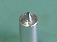
The carbide was supplied by a double ended scribe and M4 setscrews.
I made a small jig to forge a 0.4mm radius in the end of the setscrew. The radius in the setscrew is burnished and polished to 0.5microns.
The scribe is removed, radiused (0.1mm) and polished to 0.5microns. For the $10.00 spent and 2 days building jigs and polishing, these work better than the $700 of sapphire/carbide I bought.
Setscrew - the green dots are the reflection of the microscope LED's.
Attachments

I really appreciate the honesty.The only way of using sapphires is to use big ones which are kind of expensive and really difficult to polish and drill for which you'd need way more expensive jewelry tools.I investigated this path and it would cost around 7....10 000 dollars to make suitable ones from scratch , an investment i couldn't afford...There are still ways of using partly polished industrial ones drilld and cut with a laser.In the end carbide is used since the 70's for toneram gimballs with reasonable success...so no real need to take the most difficult path.I think the swiss Stellavox reel to reel tape machine was the only audio equipment using ruby guides, but reel to rell machine parts don't move randomly or by people's hand, they have very tightly controlled and reduced in length movement.
Maybe it would have been better to use the springed Vee jewel pivots to prevent fractures.
Maybe it would have been better to use the springed Vee jewel pivots to prevent fractures.
Last edited:
I didn't make the sapphire pivots I bought them from True Point in the UK. They are highly polished instrument pivots.
These DIY pivots have 4mg sensitivity in the vertical plane. Better than most high end tonearms. They are very rigid to go along with the rest of the arm.
DIY Tonearm sensitivity 4mg - YouTube
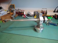
It's been operational for a couple of weeks now.
Technics SP10 with DIY Tonearm - YouTube
These DIY pivots have 4mg sensitivity in the vertical plane. Better than most high end tonearms. They are very rigid to go along with the rest of the arm.
DIY Tonearm sensitivity 4mg - YouTube
It's been operational for a couple of weeks now.
Technics SP10 with DIY Tonearm - YouTube
- Home
- Source & Line
- Analogue Source
- DIY 4 point pivoting arm