I have two extra boards for sale. Cost is $15.64 each plus shipping costs. PM me if you are interested.
PM Sent!
Cheers,
Geary
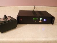
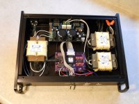
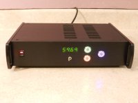
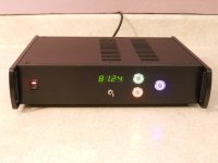
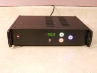
This is my version of the SG4. I built the dual phase version using the MK154 amp for use with a VPI Scout table. I bought the case on e-Bay and machined the front panel for a remote mounted LED display. The 3 lighted buttons parallel the buttons on the PCB: Green for UP, Red for DOWN and Blue for STBY. The toggle switch changes between 33 and 45 RPM.
Attachments

That is a very professional looking DIY project , nice job.
Have you had a chance to try it yet with the Hurst motor.
Have you had a chance to try it yet with the Hurst motor.
This is my version of the SG4. I built the dual phase version using the MK154 amp for use with a VPI Scout table. I bought the case on e-Bay and machined the front panel for a remote mounted LED display. The 3 lighted buttons parallel the buttons on the PCB: Green for UP, Red for DOWN and Blue for STBY. The toggle switch changes between 33 and 45 RPM.
Wow that is nice! Can you talk more about the machining? That's where i always fall down in my builds.
Have you had a chance to try it yet with the Hurst motor.
Yes, I'm using it with my VPI Scout w/Hurst motor. 33 RPM works perfectly and it is easy to dial in the phase for lower vibration. At 45 RPM, it works but not all the time (sometimes the motor does not run). I've been playing with the brass collar on the motor; that seems to have some effect on it.
Wow that is nice! Can you talk more about the machining? That's where i always fall down in my builds.
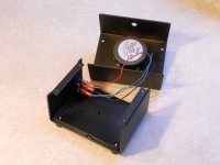
All of the components are mounted on stand-offs on the floor of the case. I marked the hole locations for the circuit boards using a sharp pencil in the mounting holes in the PCB. From there I center-punched and drilled the mounting holes. I marked the mounting holes for the chip amps after the PCB was installed on stand-offs. This requires the case to be assembled-disassembled several times, but it results in accurate placement.
The holes in the front panel were the most difficult, especially the rectangular ones for the power switch and the display. I traced the outline of the display with a pencil and I started with small drills and worked up to the larger diameters in several steps. With most of the metal removed by drilling, I used various files to flatten the opening and square the corners. The round holes were easier, but I drilled them in several steps starting with 1/4"->3/8"->5/8".
Yes, I'm using it with my VPI Scout w/Hurst motor. 33 RPM works perfectly and it is easy to dial in the phase for lower vibration. At 45 RPM, it works but not all the time (sometimes the motor does not run). I've been playing with the brass collar on the motor; that seems to have some effect on it.
Good to know, kind of surprising though.
I have my custom built deck driven with the Hurst running from a Eagle PSU and it works every time on 45 RPM.
It does make some cogging noise though until it gets up to speed though
Gonna build this!! Thanks for sharing your expertise and effort Bill!! I have already ordered a couple of the SG4 chips from Twystd. Sent a PM for a couple of boards. Now trying to finalize the BOM and get the parts orders off.
Couple of questions...
Any performance difference between the LM3886TF and TDA7492 amplifier boards? My preference would be TDA7492 for the cooler Class D operation.
It would appear that I would need some different components to support the TDA7492. Amgis L01-6362 12V toroidal transformer and a 24vdc SPS.
I have several Dell and Toshiba power supplies. They are well regulated, but output is only 19.5VDC 90W. Can I use this PS or am I better of the get the new 24VDC PS?
I have a VPI SDS and look forward to the comparison. I have several TT's, with which to use the controller. (Thorens TD124, TD150, TD160, Empire 208 and VPI TNT IV & HW19...don't ask why!!!!) I also have a later build of the old VPI PLC. Both VPI units provide significant improvements with my TT's. But both are old and NLA. I don't know if VPI still offers repairs on the SDS, but I know not on the PLC. The only issues I have ever had with the VPI units was the PLC. That was solved by replacing a couple of electrolytic caps and reseating chips.
The SDS and PLC are the only components in my kit that I have not built. All tube amplification and tube based DAC, so I am really jazzed about building the SG4.
Cheers,
Geary
Last edited:
Geary-
I like the TDA7492 better than the LM3886 amps. Not only is more efficient and easier to keep cool, it seems to be lower distortion and drives the inductive loads easier. I also like the Amgis toroids better than the the IE construction xfmrs; more efficient and better load regulation (also, no mechanical humming).
You could use the 19.5V Toshiba supplies, but you will need a 9 or 10V secondary toroid for the step up if you do. Generally, the higher the supply voltage the easier it is to produce 120VAC output.
The SDS was a decent box, but IMHO, overpriced. The PLC is not in the same league; it output distorted square waves with lots of ringing. It was designed similar to the old 12V inverters from the '70s that converted your car battery into 120V for drills etc. It makes a better parking brake than a power supply.
Geary-
I like the TDA7492 be
You could use the 19.5V Toshiba supplies, but you will need a 9 or 10V secondary toroid for the step up if you do. Generally, the higher the supply voltage the easier it is to produce 120VAC output.
I'm getting confused, my head is spinning. If using The tda7492 with 24Vdc ,how does one determine the secondaries on the output transformers? The lp12-1900 secondaries in series gives 12.6Vac series. The amgis L01-6362 secondaries in parallel give 12Vac. So should i be looking for 12Vac secondaries?
If so, could I use these Antek toroids? AN-0212 is a 25VA toroid ($11) with dual secondaries of 12Vac each. I'm going to be ordering other Antek stuff for another project and thought i could throw these in.
I think it's time i jump in and just start ordering parts. I hate analysis paralysis.
When using a xfmr for step up (instead of step down), you need to look at 2 things: turns ratio and secondary voltage (primary voltage is a fixed target at 115VAC). If the secondary is rated for 12VAC, it is done so at rated output (ie 25W). The "apparent" turns ratio is 115/12 or 9.6x. A 12V secondary rated for 25W will actually have an open circuit voltage of ~15V RMS so the turns ratio is ~7.66x. In order to drive the primary to 115VAC (no load), you will need to provide at least 15VRMS into the secondary (more if you load the primary with a motor). 15VRMS is 42.5VPP which will require at least 45VDC power supply rails if using a conventional push-pull amp. In reality, a 48VDC supply would be minimum needed to do the job. If you use a bridge tied load (BTL) amp, the output voltage is effectively doubled, so you would only need 24VDC supply rails. The TDA7492 has BTL outputs, so a 24VDC supply is adequate for a 12V secondary xfmr. The LM3886 amps are conventional push pull with a supply rail of ±15VDC and can only produce ~22VPP output before distorting (7.8VRMS) so it requires a xfmr with a 6VAC secondary (which would have ~8V RMS unloaded output).
My comment about the higher the supply voltage the better, is based on the impedance of the motor that is transformed by the xfmr based on the secondary voltage. A 10W motor will have a static impedance of ~1322 Ohms (115^2/10). The xfmr converts the impedance as the square of the turns ratio. A 12VRMS secondary has a turns ratio of 7.66 so the impedance presented to the amp is ~22.5 Ohms (1322/7.66^2). A 6VRMS secondary has a turns ratio of 15.32 so the impedance presented to the amp is 5.63 Ohms or 4x lower. As the motor power increases, you can see what happens to the load impedance.
If Geary used a 19.5VDC supply, the TDA7492 would only be able to produce ~18VPP (BTL) which is equivalent to 36VPP (or 12.7VRMS) which would be the unloaded output of a 9 or 10V secondary xfmr.
So the short answer is: If you use the TDA7492, use a 24VDC power supply and use 12VAC secondary xfmrs.
Ugh! I typed out a nice response and lost it. Thank you again for the detailed response, I learn more all the time. I always forget impedance when dealing with transformers. So you have removed much of my paralysis - I'll go buy a TDA7492, 24Vdc supply, and a couple of those antek transformers. 🙂
My SG4 boards have finally arrived!! Now to start assembling. South African C&E very inefficient indeed. Still waiting for encoders and amps.
Hi all,
I reckon its ideal for a specially built up chip amp but can I use some >60W Car audio power amplifier instead to drive suitable transformer to 230V output? My tt is with a 230V Hurst PB motor.
I reckon its ideal for a specially built up chip amp but can I use some >60W Car audio power amplifier instead to drive suitable transformer to 230V output? My tt is with a 230V Hurst PB motor.
Hi all,
I reckon its ideal for a specially built up chip amp but can I use some >60W Car audio power amplifier instead to drive suitable transformer to 230V output? My tt is with a 230V Hurst PB motor.
See post #153 above re: voltages and xfmrs.
Since all car stereo amps are powered by 12VDC supply rails, the very most you could drive the secondary with is 12VPP. If it is a bridge amp output, this is 8.5VRMS, so you would need a 6V secondary (or less). A 6V (8.5) to 230V xfmr will have a turns ratio of 27x, so driving a 10W 230V motor (5290 Ohms) will present a 7.25 Ohm load. If it is not a BTL amp, you would need a 3V secondary.
Hi Pyramid,
Thank you very much for your enlightenment and good explanation.
It was a passing thought and toying with this idea of using a car amp since I could easily find a used one locally. 🙂
At the risk of further confusing everyone, it should be noted that when using a BTL (bridge) amplifier i.e. the TDA7492, the impedance seen by the amplifier is half of the actual load impedance, so you should factor that into your calculations. The actual load impedance can still be calculated by measuring (or computing) the motor impedance and dividing by the square of the turns ratio, which is ~ primary voltage/no-load secondary voltage.
Parts ( Chips and boards available)
I now have both chips and boards available again for anyone outside of the US to order. As before due to postal charges these are a little more expensive than in the US:-
SG4 chip. £10.00
Circuit board £20.00
SG4 chip + board £30.00
All the above prices exclude post and packing which will be £3.00 for UK, £4.00
for Europe, and £5.00 for anywhere else in the world.
I prefer to only supply single boards, if you require more than 1 board I
would suggest you buy them direct from Oshpark as it will work out cheaper for you.
I will of course supply multiple chips as required.
As it is some time since my last supply can I please ask anyone who requested recently to
resend their request.
Ralph
See post #153 above re: voltages and xfmrs.
Since all car stereo amps are powered by 12VDC supply rails, the very most you could drive the secondary with is 12VPP. If it is a bridge amp output, this is 8.5VRMS, so you would need a 6V secondary (or less). A 6V (8.5) to 230V xfmr will have a turns ratio of 27x, so driving a 10W 230V motor (5290 Ohms) will present a 7.25 Ohm load. If it is not a BTL amp, you would need a 3V secondary.
Just as an add-on to the above, some 'high power' car stereo power amplifiers use a mosfet switcheing circuit to raise the internal psu voltage. These often also have the advantage of accepting a 'speaker level' input making it feasible to use one of these directly from the SG4 IF with a 12~120 or 12~230 V transformer. They are often also specified to be able to drive a 2Ohm load.
As they vary enormously in quality it's very much a 'try at your own risk' scenario.
This is my version of the SG4. I built the dual phase version using the MK154 amp for use with a VPI Scout table. I bought the case on e-Bay and machined the front panel for a remote mounted LED display. The 3 lighted buttons parallel the buttons on the PCB: Green for UP, Red for DOWN and Blue for STBY. The toggle switch changes between 33 and 45 RPM.
If you do not mind me asking, do you have PNs and source for the push button switches?
- Home
- Source & Line
- Analogue Source
- DIY 4 Phase Sinewave Generator for Turntable Motor Drive