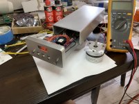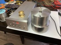

Straight forward build and excellent documentation!
Lower cylinder is poured lead from a previous motor
Holes and channels near shaft allow heat to vent
Brass spindle needs returning as its not true enough
Display works just can’t capture total digit count
For my Versa Dynamics model 1.2 Turntable to
Replace the stepper designed drive system
Hope it will drive the high drag platter design
Thanx Pyramid !
Regards
David
Great looking build!
What's up with the display? If the other digits are displaying correctly, the display driver is OK and those 8 connections are OK. If missing a digit, one of the common cathode connections is bad, one of the 2N7000 MOSFETs are bad or a connection between uP and transistor. The display is multiplexed, so each segment in all 4 digits are connected in parallel. Only one display digit is actually enabled at any one time.
What's up with the display? If the other digits are displaying correctly, the display driver is OK and those 8 connections are OK. If missing a digit, one of the common cathode connections is bad, one of the 2N7000 MOSFETs are bad or a connection between uP and transistor. The display is multiplexed, so each segment in all 4 digits are connected in parallel. Only one display digit is actually enabled at any one time.
Working on my SG4+MA3D. Everything seems to be working correctly at 33rpm mode - frequency, voltage, display, up/down/stby key functions etc. The problem is cannot switch to 45rpm mode/setting. It's always stuck at one frequency. When I measure pin 19, it will toggle to 0V when the switch is closed. But neither the display nor the frequency change. Any advice?
Is pin 19 at 5VDC when the switch is open? Also, make sure the contact on the socket is making a solid connection with the pin on the uP (sometimes if the contact or the pin is bent it looks OK, but is not making contact).
Is it possible both 33 and 45 RPM are set to the same frequency? Try switching to 45 RPM, change the frequency with the up/down buttons, then switch back to 33.
It is possible the uP is faulty; do you have another to try?
Is it possible both 33 and 45 RPM are set to the same frequency? Try switching to 45 RPM, change the frequency with the up/down buttons, then switch back to 33.
It is possible the uP is faulty; do you have another to try?
Thanks for your reply.
I'm probing at pin 19 directly, and also at the resistor. it is 5V when open and 0V when closed. I have tried changing the frequency at each position of the 33/45 switch and they always change together. I have also tried another uP and the result is the same.
I also tried doing a factory default mode, which it display FAC and DONE, and the frequency display 60.00 when I switch 33/45.
Just want to check that I can change 33/45 on the fly. Anyhow, I have tried to change it in standby, when off, when running; all with the same result.
In Phase and voltage adjust mode, when I toggle pin 19 voltage, neither the display or the output waveform change. I can make phase and voltage adjustment and save them though, but there is only 1 set of settings.
I have also tried strapping it for 50Hz mode. The display and output both show 50Hz, but toggling 33/45 make no change.
One other thing that I tried is short pin 19 directly to ground. Still make no difference. It almost as if the 45 mode is absent from the uP. Or it is not pin 19 that is controlling it?
One anomaly that is observed is that there is a 150mV pk-pk 18.432MHz waveform on pin 19. I think it may just be crosstalk from the adjacent clkout pin.
btw, these are fresh v1.03 parts that I received last week from Seth.
I just checked the PCB layout and the firmware against the schematic. It looks like there is an error on the schematic; the 33/45 switch goes to pin 18, not 19. If you used the Gerber files in the OP to make the PCB, it should be correct (switch is connected to pin 18).
Check that the ground pin (22) is making good contact. I've seen a similar Atmel uP run without a ground connection, it was getting enough current leaking through the other pins to operate, though not correctly.
Check that the ground pin (22) is making good contact. I've seen a similar Atmel uP run without a ground connection, it was getting enough current leaking through the other pins to operate, though not correctly.
Sorry for the confusion. I most likely drew the schematic to pin 19, but when I did the PCB layout, found it easier to connect to pin 18 instead and never updated the schematic (I used one program for schematic capture and a different package for PCB layout, so they were not linked or do not back annotate automatically).
This looks like a great piece of engineering! I am curious, how difficult would it be to add an option for a third speed, i.e. 78 rpm?
Depending on the motor, it most likely is not practical. The speed selection is currently done in hardware (toggle a pin high/low for 2 speeds); it would have to be moved to software where you use the STBY button to toggle speeds.
With a 50Hz motor/pulley, the frequencies become 50/67.5/117Hz for 33/45/78; the display does not have enough digits for this. With a 60Hz pulley, the freqs are 60/81/140.4Hz.
An AC synch motor designed to operate at 500/600 RPM for 33 RPM platter speed will not turn at the frequencies needed for 78 RPM. A 3 phase BLDC motor will, but the voltage will need to be different for all 3 speeds.
The easiest solution is to use a 78 RPM pulley (some of the TT mfrs make them specifically for this purpose) or buy the Condor motor controller from SOTA, as it will do all 3 speeds.
I would edit my previous post, but it is still pending admin approval. I have a second question. Since the output is DC coupled, does it require a high pass filter before being sent to the (amplifier and then) motor?
The signal from the SG4 to the amplifier must be AC coupled (capacitively); most ready made amp PCBs have caps on the inputs, but if not, they should be added. The value will depend on the input impedance and the lowest frequency at which the motor will operate. The corner frequency (1/[2*PI*R*C]) should be ~50% of the lowest operating frequency (or lower).
Between the amp and the motor (or transformer): If the amplifier output is single ended and run from a single supply voltage, it will need to be AC coupled. If run from dual supplies or is configured for a Bridged output (BTL), AC coupling should not be needed as long as the DC offset voltage at the outputs are nearly identical (BTL) or near zero (dual supply) (<20mV offset).
Okay, I figured this was the case. I am a scientist but no electrical engineer so I wanted to hear it from the horses mouth. "The three most dangerous things in the world are a programmer with a soldering iron, a hardware type with a program patch, and a user with an idea."
"The three most dangerous things in the world are a programmer with a soldering iron, a hardware type with a program patch, and a user with an idea."
Hmmm....I do software and hardware design, so I'm probably twice as dangerous!
One of my favorite quotes: "If carpenters built houses the same way programmers write software, the first woodpecker to come along would destroy civilization"--author unknown
- Home
- Source & Line
- Analogue Source
- DIY 4 Phase Sinewave Generator for Turntable Motor Drive
 done
done