Hi Pyramid,
Is there a possibility that a RoadRunner DIY version might become available? I have searched all over for a unit on the web, but can't get one at a reasonable price. The businesses that have bought all available stocks, have hiked the pricing by at least 50% to 100%, making it a lot less affordable.
Regards,
Kevin
Hi Pyramid,
Is there a possibility that a RoadRunner DIY version might become available? I have searched all over for a unit on the web, but can't get one at a reasonable price. The businesses that have bought all available stocks, have hiked the pricing by at least 50% to 100%, making it a lot less affordable.
Regards,
Kevin
There is a thread in this forum for a DIY version that seems to produce the desired readings: http://www.diyaudio.com/forums/analogue-source/301609-digital-tachometer-record-player-lcd-display.html
Looking at the code segments they provided, there may be some room for improvement. The Arduino platform seems reasonably priced.
The SG4 does not accept input from a tach (either RR or DIY versions), so use of these devices will be limited to monitoring and manually correcting the speed.
Pyramid:
Yes, for both speeds. I'd love to fix this -- whatever the problem is, I don't want it to affect my ability to play 45s on those rare occasions when the opportunity arises -- but the reality is that the ratio of 33 disks to 45 disks in my collection is probably 100:1.
If you're uncertain as to what could be causing this, I have a possible work-around: what if I added something to those 2.2k resistors on the MK-154 amp in order to get the 60 hz voltage from 91.2 VAC up to 115 VAC, and then dialed back the 80 hz reduced output level to 115 VAC as well?
Either way, can I safely add 1k resistors in series with the 2.2k resistors on the MK-154 amp or is that too much (assuming you don't have another solution to offer)?
Regards,
Scott
Is the reduced output level for each speed set to max (128)?
Yes, for both speeds. I'd love to fix this -- whatever the problem is, I don't want it to affect my ability to play 45s on those rare occasions when the opportunity arises -- but the reality is that the ratio of 33 disks to 45 disks in my collection is probably 100:1.
If you're uncertain as to what could be causing this, I have a possible work-around: what if I added something to those 2.2k resistors on the MK-154 amp in order to get the 60 hz voltage from 91.2 VAC up to 115 VAC, and then dialed back the 80 hz reduced output level to 115 VAC as well?
Either way, can I safely add 1k resistors in series with the 2.2k resistors on the MK-154 amp or is that too much (assuming you don't have another solution to offer)?
Regards,
Scott
I assume the 10K pot is at maximum as well?
If you replaced the 22 K resistor with 2K2, either add 1K in series with the 2K2 or replace it with 3K3.
If you paralleled the 22K with 2K2, either add 1K8 in series with the 2K2 or replace it with 3K9.
Either of these solutions will most likely produce slightly more than 115VAC. Use the 10K pot to trim it down to 115 at 33 RPM when set to 128. Then reduce both SG4 settings for 33 and 45 RPM for the desired running voltage.
I'm still concerned about the difference in output between 60Hz and 81Hz. The MK-154 should be flat down to 20Hz. I would feel better if you looked at the output of the MK-154 with a scope.
Also, measure each of the outputs (L & R) from the MK-154 with the output transformer disconnected from the amps. Your target is to get 8.4VRMS out of the amps.
Pyramid:
Yes, the 10k pot is at its maximum. I don't have a scope. The MK-154 measures 6.12 VAC (Left Channel) and 6.07 VAC (Right Channel). I'll add a 1k resistor in series with the 2.2k resistors on both channels this weekend and report back on the results.
Thank you, by the way, for the support!
Regards,
Scott
Currently looking for a board and uP, thought I'd try here first to see if anyone had both before going and ordering three boards and the uP separate.
Pyramid:
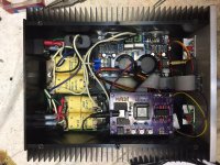
I worked from home today and took a break to complete the corrections to the SG-4. Additional 1k resistors were added, the voltages at both 60hz and 80hz were adjusted and everything is working beautifully.
I'd been agonizing over your Falcon for a few years and was thrilled when you announced the SG-4 project. The SG-4 fills a void (albeit one of your own creation -- a superior, affordable turntable motor controller). diyAudio is a far better place because of the generosity of people like you and I hope you find retirement to be a happy, productive time. Thank you for making this project available!
Regards,
Scott
Attachments
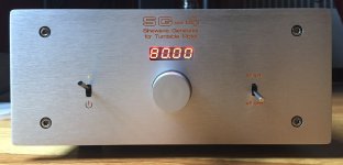
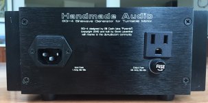
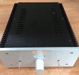
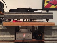
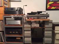
Love your engraving work and case tweaks. Very slick! Nice turntable build as well. My own setup is almost as messy as Mike Fremer's basement. 😛
And it seems you're close by to me as well. Nice! If you had any of your casework done locally, please do let me know. If cash ever frees up (HAH!), perhaps I could get some beautification done.
And it seems you're close by to me as well. Nice! If you had any of your casework done locally, please do let me know. If cash ever frees up (HAH!), perhaps I could get some beautification done.
Last edited:
Glad it worked out OK & thanks for the kind words.
Agree with Packgrog about the faceplate and engraving; yours is one of the best looking controllers I seen so far, including a few that I've built.
Where did you have the front/back panel made?
Agree with Packgrog about the faceplate and engraving; yours is one of the best looking controllers I seen so far, including a few that I've built.
Where did you have the front/back panel made?
Pyramid:
Front Panel Express. I've been using their services now for about 10 years. Their prices are a little high but I don't build that many projects and tend to use what I build for a long time, so things even out. Given my general lack of knowledge about circuit design, focusing on the cosmetics (as lame as that might be) helps me to personalize the things I build.
If anyone is interested in my .fpd files, feel free to PM me.
Regards,
Scott
@SRMcGee, that is a beautiful build. Well done. 🙂
A question to you, and anyone else who uses the rotary encoder in place of the pushbutons for the SG4 - how do you access some of the "advanced" features of the SG4 with the rotary encoder?
I have yet to build an SG4 (awaiting parts), but reading through the assembly instructions I was wondering how one accesses, for example, Phase Adjustment, with an encoder?
The instructions state "holding the UP button while exiting standby", and I wonder how that can be done with the encoder?
Since those functions are USUALLY set once (or twice) and forget them, they have to be accessed with the push button switches on the PCB, which can be used in parallel with the rotary switch.
For instance: To select reduced voltage mode, press and hold the DN button on the PCB while exiting Standby mode (short press of the rotary encoder switch or the STBY button). The rotary encoder can then be used to increase or decrease the value (as well as using the UP/DN buttons).
For instance: To select reduced voltage mode, press and hold the DN button on the PCB while exiting Standby mode (short press of the rotary encoder switch or the STBY button). The rotary encoder can then be used to increase or decrease the value (as well as using the UP/DN buttons).
Digital tachometer
Hi Bill,
Many thanks for the pointer, much appreciated. I purely want to monitor the platter speed. You did mention somewhere in the SG4 forum (if I recall correctly) that the unit won't be able to take feedback, and provide correction.
Your mention of doing it all in assembler would be an interesting project. My major problem is not having looked at any form of coding since 1989. However an Arduino is probably the simplest way to get back into that, I hope. Will try my hand at that when time and my brain permits it. 😱
Kevin
There is a thread in this forum for a DIY version that seems to produce the desired readings: http://www.diyaudio.com/forums/analogue-source/301609-digital-tachometer-record-player-lcd-display.html
Looking at the code segments they provided, there may be some room for improvement. The Arduino platform seems reasonably priced.
The SG4 does not accept input from a tach (either RR or DIY versions), so use of these devices will be limited to monitoring and manually correcting the speed.
Hi Bill,
Many thanks for the pointer, much appreciated. I purely want to monitor the platter speed. You did mention somewhere in the SG4 forum (if I recall correctly) that the unit won't be able to take feedback, and provide correction.
Your mention of doing it all in assembler would be an interesting project. My major problem is not having looked at any form of coding since 1989. However an Arduino is probably the simplest way to get back into that, I hope. Will try my hand at that when time and my brain permits it. 😱
Kevin
Pyramid:
I apologize if this is (and further sparks) an off-topic distraction, but two questions dawned on me:
First, could the SG-4 be modified to serve as the heart of a clean power / power regeneration system like the PS Audio Power Plants (http://www.psaudio.com/perfectwave-p5-power-plant/)?
Second, do you think it would be a worthwhile exercise?
Regards,
Scott
Pyramid:
I apologize if this is (and further sparks) an off-topic distraction, but two questions dawned on me:
First, could the SG-4 be modified to serve as the heart of a clean power / power regeneration system like the PS Audio Power Plants (http://www.psaudio.com/perfectwave-p5-power-plant/)?
Technically, it could. Since people use those supplies to power phono stages and other critical components, I'm guessing Class D amps would not be acceptable. To do a 100/250/500W supply with class AB amps would involve a lot of power (and heat).
Second, do you think it would be a worthwhile exercise?
Regards,
Scott
Creating a supply for a 15W motor is fairly fool-proof. Even if something goes wrong, it's not likely to be catastrophic. Doing a high power supply is a different kettle of fish and I wouldn't recommend it for the DIYer. The consequences of a failure at those power levels could be dangerous and expensive.
Technically, it could. Since people use those supplies to power phono stages and other critical components, I'm guessing Class D amps would not be acceptable. To do a 100/250/500W supply with class AB amps would involve a lot of power (and heat).
Creating a supply for a 15W motor is fairly fool-proof. Even if something goes wrong, it's not likely to be catastrophic. Doing a high power supply is a different kettle of fish and I wouldn't recommend it for the DIYer. The consequences of a failure at those power levels could be dangerous and expensive.
Pyramid:
Thank you. Perhaps I ought to stop noodling after a couple glasses of Malbec.
Have a lovely holiday,
Scott
@Pyramid,
it seems that the Lite-ON 7-segment display is out of stock with the usual suspects. Mouser expects a re-stock end of August.
I have been searching for compatible replacements online, but with little luck - common cathode, 7-segment, 4 digit, 0.3" pin row spacing.
Any thoughts on a compatible replacement?
Any of the LTC-2723x variants will work (different colors), but there doesn't seem to be much stock out there right now.
You can use a different size and mfr of display if you remote mount it and use a ribbon cable between the display and the PCB. It will most likely have a different pin-out, so you need to create a conversion table to get the correct wire from the ribbon cable to the correct pin on the display. Be aware the ribbon cable wires are not connected to pins 1-2-3-etc., they are 1-16-2-15-3-14-etc.
You can use a different size and mfr of display if you remote mount it and use a ribbon cable between the display and the PCB. It will most likely have a different pin-out, so you need to create a conversion table to get the correct wire from the ribbon cable to the correct pin on the display. Be aware the ribbon cable wires are not connected to pins 1-2-3-etc., they are 1-16-2-15-3-14-etc.
- Home
- Source & Line
- Analogue Source
- DIY 4 Phase Sinewave Generator for Turntable Motor Drive