I am about to start this long cherished project. I tried to go through the overwhelming search procedure but found no recent posts prior to starting this new thread, I'm afraid.
Also I googled a lot but I am decisively indecisive on which schematic to select.
Since it is a DIY project for me, I need a schematic
1. that uses commonly available parts, no odd component values, and performs very well
2. made and thoroughly tested to entire satisfaction by our experienced users so that I could hold your always extending helping hand for help as and when it is required
3. if any Eagle project files or design spark files exist ( top and bottom layers)
since I use old toner transfer method to make my PCB.
Eagerly awaiting your valuable inputs regarding a circuit that is ready to build, tested and giving professional result.
Thank you all. 🙂
Update:
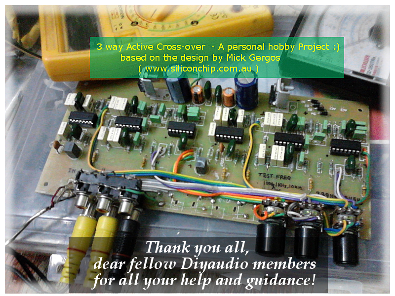
The hobby project is a finally done!
It is based on an article by respected Mr. Mick Gergos of www.siliconchip.com.au .
It is full of exhaustive and minute details and and an extremely well thought out guidance.
http://archive.siliconchip.com.au/cms/A_30278/article.html
Thank you so much friends for all your help. 🙂
Also I googled a lot but I am decisively indecisive on which schematic to select.
Since it is a DIY project for me, I need a schematic
1. that uses commonly available parts, no odd component values, and performs very well
2. made and thoroughly tested to entire satisfaction by our experienced users so that I could hold your always extending helping hand for help as and when it is required
3. if any Eagle project files or design spark files exist ( top and bottom layers)
since I use old toner transfer method to make my PCB.
Eagerly awaiting your valuable inputs regarding a circuit that is ready to build, tested and giving professional result.
Thank you all. 🙂
Update:
The hobby project is a finally done!
It is based on an article by respected Mr. Mick Gergos of www.siliconchip.com.au .
It is full of exhaustive and minute details and and an extremely well thought out guidance.
http://archive.siliconchip.com.au/cms/A_30278/article.html
Thank you so much friends for all your help. 🙂
Last edited:
yes Andrew.did you read esp and linkwitz?
My current one is from ESP project 123 which is a 2 way system.
And I am lost with Linkwitz due to odd vaules.
Thank you for your quick response.
Since it is a DIY project for me, I need a schematic
if any Eagle project files or design spark files exist ( top and bottom layers)
since I use old toner transfer method to make my PCB.
Silicon Chip Online - Active 3-Way Crossover for Loud Speaker Systems
Did you try the project personally ? How is the performance ?
It is well written project. Everything is available there. My advice is to please take a time to read completely.
Personally I build 2 way active crossover with eq. And I can turn it into 3 way by fitting passive filter at high-pass output. I like passive component for mid & tweeter.
But this may not suitable you. You asked for "3 way active crossover"
Best Regards.
Thank you Pra3718. I will go through the page and keep you updated about my progress.
I saw you are from India too. Could you please suggest what speakers set I can use as you know the concern of availability of branded speakers and cost here in India , I guess?
I saw you are from India too. Could you please suggest what speakers set I can use as you know the concern of availability of branded speakers and cost here in India , I guess?
Last edited:
There is good mfg. at delhi. Please search for. I happy with it. Cheap and good. After successful build you can replace with better one.
There is good mfg. at delhi. Please search for. I happy with it. Cheap and good. After successful build you can replace with better one.
Thank you Pra3718.
Earlier I used Philips, Bolton, YP, and some local make. Philips and Bolton were better sounding. At present I am using panasonic not bad.
I made a 2 way active system and realized I was really missing something with low cost commercial 2/3 way passive solution. Hence I am trying to upgrade to a 3 way one despite the challenge involved.
Many suggested that a 3 way system might not perform well in a small listening room(ref: youtube videos on which speakers to choose).
But the sound of my DIY floor standers in tandem with this active system with 4 X TDA2050 are simply loved by every listener ( 15 out of 15 so far). Thats an inspiration for the DIY-ers like us
Thank you again
3 way active crossover
thanks.
sudhir
I have made and used above said crossover. It has very good performance...compare it with esp project...It is almost same.All parts are easily available & every detail including pcb pattern is provided on site.
thanks.
sudhir
I have made and used above said crossover. It has very good performance...compare it with esp project...It is almost same.All parts are easily available & every detail including pcb pattern is provided on site.
thanks.
sudhir
Thank you really so much Sudhir for your kind advice. I consider your this post as an encouragement.
Sometimes we face problem due to a slight inadvertent mistake in the PCB design posted on the internet . But your words really helped me to get rid of that concern.
Could you please tell me how you made the PCB ? I am a bit hesitant to use my old toner transfer method in this case as the board is large and fairly complex.
( Oh, I purchased 6 TLO74 Ics and sockets and some 1% metal resistors. And some other parts are already in my inventory. So wish me luck please 🙂 )
Attachments
Active crossover
2-Way Active Crossover with Linear Phase Response
CO3 Three Band Phase-Linear Crossover Filter Kit (Bass, Mid-range, and Treble)_Filter_Accessories Kit_Analog Metric - DIY Audio Kit
Three-way active speakers using chip amps.
ACTIVE LOUDSPEAKER SYSTEM: Subwoofer, Construction, Cabinets, Electronic Filter/Tube Crossover, Amplifiers, Units.
have fun!
regards,
Piersma
Thank you so much Piersma for your reply.
I am using a two way setup from the ESP site. I definitely found an improvement using them over my passive network that I used earlier. No biased opinion here. So I decided to use a 3 way system mainly to learn, to experiment while DIY-ing is an added pleasure.
The links are really good. But unfortunately they have hardly any readymade PCB layout design to start with ( except the kit which is the best way to make a quick start). Perhaps I can design the layout myself but I am impatient right now 🙂
The last link has a very well thought out discussion on different aspects of using Xover as I can see.
So I sincerely do appreciate your post. Thank you again. 🙂
Hi,
Unfortunately standard L/R electrical crossovers are no short
cut to high quality loudspeaker design, they are too inflexible.
rgds, sreten.
Unfortunately standard L/R electrical crossovers are no short
cut to high quality loudspeaker design, they are too inflexible.
rgds, sreten.
Thank you for your reply Sreten.
I completely agree.
That's why I am in search of a tested PCB layout as I am not so skilled.
🙂
I completely agree.
That's why I am in search of a tested PCB layout as I am not so skilled.
🙂

I talked to a PCB making company in my locality.
Hopefully I will get the PCB in a week or so.
I will keep everyone updated about my progress.
Thank you all . 🙂
Hopefully I will get the PCB in a week or so.
I will keep everyone updated about my progress.
Thank you all . 🙂
Last edited:
Hi,
It is not about PCB's. It is about the ideal electrical transfer functions
looking nothing like any standard textbook electrical filters, used to
achieve with the drivers and box the correct acoustic responses.
rgds, sreten.
It is not about PCB's. It is about the ideal electrical transfer functions
looking nothing like any standard textbook electrical filters, used to
achieve with the drivers and box the correct acoustic responses.
rgds, sreten.
Thank you sreten.
Could you please recommend some reading material in this regard so that I can understand it better?
I need them because my next work is to tune up my DIY Floorstanders. They sound very nice "by chance".
I need to know what more can I do to optimize their acoustic response.
Thank you for your feedback.
Last edited:
- Status
- Not open for further replies.
- Home
- Source & Line
- Analog Line Level
- DIY 3 way active crossover: as Christmas Holiday Project