Depending on the LTP´s tail current you are using, the 10K you suggest is probably too low.
Suppose 1mA, then the differential input impedance could easily be ca 50K, making the total load some 24k.
This can't be done without severely corrupting the FR.
When you send me the details of you input stage, I can give you a better advice.
Hans
Suppose 1mA, then the differential input impedance could easily be ca 50K, making the total load some 24k.
This can't be done without severely corrupting the FR.
When you send me the details of you input stage, I can give you a better advice.
Hans
If the threshold number is something you came across in published research then it should be what it generally means in psychoacoustics and science. IOW if properly scientific, it is an estimate of an average for a population, not a hard limit. If one thinks about it, how could it be anything else? Its not possible to test millions and millions of people to find a hard limit. In reality a few hundred people or something like that are often used to produce an estimate of the average threshold for a population represented by the test subjects.Assuming that you are referring to tracking errors, “below auditory threshold” means...
For one definition: "The level above which sound intensity, at any specified frequency, must rise in order to be detected by the average human ear."
https://glossary.ametsoc.org/wiki/Threshold_of_audibility#:~:text=The level above which sound,by the average human ear.
Of course not. The point I was trying to make was that .05% difference in a sound is, so far as I know, not an unusually low number for some people to be able to discriminate. Therefore I wonder if there is some scientific basis for setting it to zero, or rather is that an approximation that seems reasonable to you but without supporting evidence? IOW is it something justified by any references cited in your paper?This figure, or however low it may be, should not in any way be confused with non-linearity or distortion.
Note: Not trying to troll you here, just trying to figure out precisely what you mean by some of what you say.
One question from interest but no knowledge : As references are all to MM, is there any implication that things are fundamentally different for MC?
Mark, playing with words may be one of your favourit hobbies, however in this case you know very well what I meant.
Hans
Hans
It is around 1mA split between each NPN in the LM394. There is no noise that isn't overwhelmed by vinyl artifacts. A bigger issue is that applying MM signals across the bases without feedback can generate unacceptable non-linearities. Yet because harmonics are generated in a pre-RIAA network they become attenuated in a downward slope when RIAA correction is applied, the higher harmonics being down substantially. In contrast IM products can be amplified by RIAA correction. As an example if acoustic notes are played close together at a higher frequency the difference frequency generated by the existence of a non-linearity becomes amplified by RIAA, being at a higher gain at lower frequencies.If the input impedance is that low, the tail current must be far above the noise optimum.
It seems that in order to reduce IM distortion artifacts, or DC shifting as a result of amplitude modulation of single frequencies, pre-RIAA networks should have good symmetry to limit the square law non-linearities. Hence the differential amplifier.
Yes. You can add emitter degeneration resistors to increase the input impedance.
There can be some benefit to that, although the network is a battery powered device. Emitter degeneration would reduce gain, hence signal amplitude to the subsequent would be lowered, as potentially to diminish the signal to noise ratio of the following network.
Hans,Mark, playing with words may be one of your favourit hobbies, however in this case you know very well what I meant.
Hans
It pains greatly me to say this because I respect a lot of what you do, but in this case it appears some of what you meant to do was to represent personal opinion as science.
You may be aware that I have been attacked repeatedly on that same basis, and criticized for not making clear what is opinion and what has supporting scientific evidence. To some extent the critics made a point that got through to me: I need to be more careful about my choice of words, not that I have become perfect at it or ever will be. Now it seems to me that to some extent the same applies to you.
Mark.
Last edited:
That’s a very good question.One question from interest but no knowledge : As references are all to MM, is there any implication that things are fundamentally different for MC?
On one hand there are large differences, such as the generator’s replacement diagram being just a coil mostly a thousand times as small with a very low resistance in series.
Because of that external cable capacity is irrelevant.
Using a transimpedance topology goes in general without any measurable loss in information transfer, indicating that also in this case like an MM loading the generator does not affect the cantilevers movement.
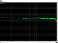
But just like an MM my MC also has a -1 dB sag at ca 4.5Khz and a resonance peak at 10Khz., see attachment.
The 16Khz dip like as before with the MM's, is coming from the test disk.
A MC's cantilever may be exposed to a smaller inertia because of not having a heavy magnet at the other side of the rod causing a different the dynamic behavior.
To get better founded information than just this, the same sort of experiments would have to be done, but since loading a MC cart is so much easier, we concentrated on the much more complex MM Cartridges.
Hans
Attachments

Dear Mark,Hans,
It pains greatly me to say this because I respect a lot of what you do, but in this case it appears some of what you meant to do was to represent personal opinion as science.
You may be aware that I have been attacked repeatedly on that same basis, and criticized for not making clear what is opinion and what has supporting scientific evidence. To some extent the critics made a point that got through to me: I need to be more careful about my choice of words, not that I have become perfect at it or ever will be. Now it seems to me that to some extent the same applies to you.
Mark.
In general you are right when defining things to avoid misinterpretation.
But when "professionals" not exactly 50% of all people, value a pivoted SAT tonearm higher than the most sophisticated tangential arm, I can only conclude that the added track angle errors seemed to be below their auditory threshold.
Sorry for having reacted the way I did, but it should have been clear that it was in no way meant as a scientific statement.
Hans
There is nothing wrong with what you did, but you should carefully tune the input impedance to ca 47KIt is around 1mA split between each NPN in the LM394. There is no noise that isn't overwhelmed by vinyl artifacts. A bigger issue is that applying MM signals across the bases without feedback can generate unacceptable non-linearities. Yet because harmonics are generated in a pre-RIAA network they become attenuated in a downward slope when RIAA correction is applied, the higher harmonics being down substantially. In contrast IM products can be amplified by RIAA correction. As an example if acoustic notes are played close together at a higher frequency the difference frequency generated by the existence of a non-linearity becomes amplified by RIAA, being at a higher gain at lower frequencies.
It seems that in order to reduce IM distortion artifacts, or DC shifting as a result of amplitude modulation of single frequencies, pre-RIAA networks should have good symmetry to limit the square law non-linearities. Hence the differential amplifier.
This can easily be done with a 100K pot in series with a LF generator connected to your amps input.
Start with R zero ohm. and gradually increase its value. At the point where the amps output is halved, the pot has the same value as your input impedance.
This way you can tune the 47K resistor to a value where the combined input impedance is 47K.
Hans
Hi MarkBill, the comments below are not directed at you specifically. Anyone who would like to offer some clarification would be great.
1. Why does it seem like 0.5% is being turned into what amounts to a very solid 0.0% for some of the explanations in this thread? If we were talking about some kinds of distortion then 0.5% might not all that small of a number?
2. Also, I'm not sure about Hans' comment as to something being 'below our auditory threshold.' Such a threshold implies 50% of the population should be able to hear below that threshold, doesn't it?
At that thread https://www.diyaudio.com/community/threads/cartridge-dynamic-behaviour.320026/post-5370025 many participants tried for evidence of the so called reciprocity btn the mechanical input, to magnetic and then to electric output of a cartridge.
There, I’ve tried three ways
One, impedance sweeps with/without stylus assy
two, recording groove info with the other channel open/shorted at cartridge pins
three, inserting a miniature coil into the space where the cantilever resides and driving it with a signal generator.
I got no evidence (MMs). If it were 0.5%, it would have shown up in the data. I can say it has to be less than 0.1%
This doesn't have to do with distortion. But even if it had, in the realms of vinyl cut/vinyl read achievable distortions, the 0.5% lies asymptotically by the 0% plot.
George
This is an area that does still intrigue me as I do have cartridges from AT where the MC assembly does appear to be more massive than the MM assembly. There should be a test that can be done to confirm the effect of this, but personally not worked out what that needs to be yet.A MC's cantilever may be exposed to a smaller inertia because of not having a heavy magnet at the other side of the rod causing a different the dynamic behavior.
It is around 1mA split between each NPN in the LM394. There is no noise that isn't overwhelmed by vinyl artifacts.
An LM394 has an hFE of the order of 500, depending on collector current, what version you use and exemplaric spread. To get the 10 kohm differential pair input resistance that you mentioned earlier, you would need a tail current of about 5.2 mA. With 1 mA, it will be more like 52 kohm or so. Assuming RIAA and A-weighting and a 500 mH cartridge, the noise optimum is a tail current of about 140 uA, but it is a very broad optimum.
.A bigger issue is that applying MM signals across the bases without feedback can generate unacceptable non-linearities. Yet because harmonics are generated in a pre-RIAA network they become attenuated in a downward slope when RIAA correction is applied, the higher harmonics being down substantially. In contrast IM products can be amplified by RIAA correction. As an example if acoustic notes are played close together at a higher frequency the difference frequency generated by the existence of a non-linearity becomes amplified by RIAA, being at a higher gain at lower frequencies.
It seems that in order to reduce IM distortion artifacts, or DC shifting as a result of amplitude modulation of single frequencies, pre-RIAA networks should have good symmetry to limit the square law non-linearities. Hence the differential amplifier.
I don't quite understand what you mean. Do you mean that the distortion of a differential pair is good enough for you while a common emitter stage's distortion is not, or that even though a differential pair distorts less than a common emitter stage, neither is good enough?
Thank you George, as ever you can find things I can't back in the forum archives. Personally even if the generator were 1% efficient there could be no appreciable damping of the cantilver from shorting the coil. This is not like a biotracer arm. And if you tried active damping the power required would melt the coils in short order even if you could work out how to do it without swamping the wanted signal.Hi Mark
At that thread https://www.diyaudio.com/community/threads/cartridge-dynamic-behaviour.320026/post-5370025 many participants tried for evidence of the so called reciprocity btn the mechanical input, to magnetic and then to electric output of a cartridge.
Hi Bill
Mark's worry is I think on the validity of the numbers discussed.
As of the efficiency of a cart, the definite answer could come from calculating the energy-in and the energy-out (known modulation velocity, known electrical load). Jacco was a master in solving such problems, alas he is not with us anymore.
George
George,
Given the complexity of the matter, with effiency figures that low, it will be hard if not almost impossible to measure a 0.1% efficiency, where all surrounding components involved also contribute in some way.
Also has to be taken into acount that efficiency is not a static figure but most likely frequency, load and temp dependent.
But the biggest question of this all is, what could be done practically with information being more precise than <0.1%.
IMHO it would be nothing more than “nice to know” 😉
Hans
You are absolutely correct Hans. The higher the optical magnification one uses, the more restrains one has to fight with for to be able to get a useful picture.
And about this 'biggest question' you mention, my opinion is, don't bother. As much as one measures and analyses, results and conclusions have to be verified by listening tests. Which brings us to the: "We've made this just for you" (A scene from the documentary "A day in B***'s life") 🙂
George
And about this 'biggest question' you mention, my opinion is, don't bother. As much as one measures and analyses, results and conclusions have to be verified by listening tests. Which brings us to the: "We've made this just for you" (A scene from the documentary "A day in B***'s life") 🙂
George
Sounds good Hans. I was previously testing a faulty device. In rechecking another LM394 in the manner you suggest it turned out a 70K resistance was required in series with the input to halve the output (this value was more in line with what Marcel indicated). This means an input resistor to ground of about 143K is required in parallel to create 47K. It turns out that the input was currently at about 28K or close to 1/2 the value it ought to have been. Do you think this lower value is significant Hans?There is nothing wrong with what you did, but you should carefully tune the input impedance to ca 47K
This can easily be done with a 100K pot in series with a LF generator connected to your amps input.
Start with R zero ohm. and gradually increase its value. At the point where the amps output is halved, the pot has the same value as your input impedance.
This way you can tune the 47K resistor to a value where the combined input impedance is 47K.
Hans
This suggests lowering the tail current, something that was and still is being considered, though gain is lowered. I like the higher output signal levels from the device I am calling the GyroHead. It is a battery powered device located beside the turntable with Interconnects to a current input mode RIAA amplifier. Using higher levels the intent is to minimize pickup effects and increase the signal/noise ratio (although lowering tail currents can dramatically increases battery life).Assuming RIAA and A-weighting and a 500 mH cartridge, the noise optimum is a tail current of about 140 uA, but it is a very broad optimum.
I don't quite understand what you mean. Do you mean that the distortion of a differential pair is good enough for you while a common emitter stage's distortion is not, or that even though a differential pair distorts less than a common emitter stage, neither is good enough?
Emotions are often difficult to sustain, like those feelings of ecstasy being around your bride before she turns (seemingly inevitably) into your wife. Notwithstanding any emotional transformations the differential network seems working very well and I am happy with it. Ultimately I can't comment definitively on the magnitude, makeup and impact of harmonic distortions, rather only to suggest that because of the subsequent RIAA filter, a differential amplifier can have a technical advantage over a common emitter stage, as specific to IM artifacts folding down into the lower registers, those that in my view can generate artificial low register content as to obscure perceived reality. Accurate bass reproduction seems would have a characteristic of not always being there, of capturing the onset and decay of notes, of more spacial resolution, and of greater vibrato when in the mixing of low register notes found in material such as that produced by organs.
It is concluded that the GyroHead doesn't possess much artificial low register content, as the power switch can be turned on and off while playing without any noticeable "thumping". The power switch is currently being used as a mute switch.
Looks like you have already answered my question Hans. I will lower the current and adjust for 47K total.Suppose 1mA, then the differential input impedance could easily be ca 50K, making the total load some 24k.
This can't be done without severely corrupting the FR.
Because being too long to put it in a posting, we have added the results in the attachment as a PDF.
Happy reading,
Wow!
It makes me so happy when new people are doing new research and challenging prior assumptions. It is really exciting, and now I feel the same exciting I had when I found Alex Korf's posts (even though I might not agree completely with Alex).
I need to give this a thorough read!
- Home
- Source & Line
- Analogue Source
- Dividing MM Carts into electrical parts with individual Transfer Functions