Since it is a wirewound resistor that caused the rise in distortion, one aspect I missed in the discussion was the other property of the resistor: wirewound... an inductor so to speak.Many years ago....... Has anybody else come across this problem or have found a technical reference to it?
Peter
The introduced fault is in the order of 10's of uV, which could easily be generated in a couple of windings... 😕
Since it is a wirewound resistor that caused the rise in distortion, one aspect I missed in the discussion was the other property of the resistor: wirewound... an inductor so to speak.
The introduced fault is in the order of 10's of uV, which could easily be generated in a couple of windings... 😕
Hi esgigt,
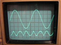
I don't see how pure inductance and/or resistance can create distortion unless their equations have non-linear terms. However, I would agree that inductance can skew the spectra of distortion components. Attached is a picture (nonlinear resistor 010.jpg) of the distortion residual showing a dominant 3rd order harmonic. To minimize the inductance of the resistor, I placed it in a 6mm ID copper tube, (which was a snug fit as shown in the attached picture nonlinear resistor 003.jpg) but there was no significant change to the inductance or the magnitude of the distortion.
Regards
Peter
Attachments
That's what I was thinking. I'd also expect the frequency threshold for the effect to vary with power level.In the absence of a better explanation I too would blame poor contacts. Thermal effects could only affect very low frequencies.
Hmm....I've no desire to witchhunt manufacturers but that seems like a misrepresented product. Do you have a brand/type marking you could quote there so one could take a look at datasheets? - if the source made them available that is.I bought some ceramic encased wirewound resistors.....I smashed one up to see inside.....It was an oxide film resistor....
Hi Ian Finch,
It is not uncommon to see a metalfilm/oxide resistor in an ceramic casing.
Here is one example:
http://www.vishay.com/docs/30218/cpcx.pdf
It is not uncommon to see a metalfilm/oxide resistor in an ceramic casing.
Here is one example:
http://www.vishay.com/docs/30218/cpcx.pdf
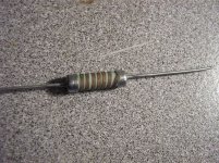
Since I haven’t seen any references posted other than that from RMJ1, I decided to do a little practical investigating myself by first removing the outer coating of insulation that covered the resistor, of which a photograph is attached (nonlinear resistor 003.jpg).
As can be seen, the connection between the tape type of resistance wire to the end caps seems to be spot welded and when I lightly stressed these connections, they appeared to be quite solid as was the lead-out wires as well.
I connected this resistor (0R05) in series with an 8R0 resistor and connected the combination (8R0+0R05) across the output of my amplifier as previously described and noted that for this particular 0R05 resistor, the measured THD was 0.14%. Previous measurements used two 0R05 resistors in series, but with this new setup, I used just one. To obtain the same input voltage to the analyzer as previously, I increased the power output, hence the higher THD level. The THD at the output of the amplifier measured 0.003%.
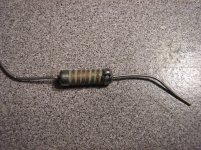
I then scraped the surface of the tape over the points where it connected to the end cap and with some flux, I soldered the tape to the end caps as shown in the attached photograph (nonlinear resistor 006.jpg).
After reconnecting the 0R05 resistor back into the circuit, I was surprised to see that the THD had dropped dramatically to 0.075%.
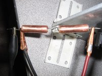
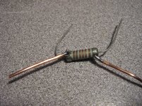
I then soldered two 1.3mm dia. solid copper wires right on top of the tape connection points to the end caps (nonlinear resistor 009.jpg) and re-ran the test again and found an even more dramatic drop in THD to 0.0045%. The distortion output from the analyzer showed a small amount of wideband noise riding on the distortion waveform. Without this noise, I’m sure the THD would be even closer to the 0.003% of the amplifier. So at this point, I feel confident that the root cause of the problem is due to the connections between the tape resistance wire and the lead-out wires with the end caps.
Regards
Peter
As can be seen, the connection between the tape type of resistance wire to the end caps seems to be spot welded and when I lightly stressed these connections, they appeared to be quite solid as was the lead-out wires as well.
I connected this resistor (0R05) in series with an 8R0 resistor and connected the combination (8R0+0R05) across the output of my amplifier as previously described and noted that for this particular 0R05 resistor, the measured THD was 0.14%. Previous measurements used two 0R05 resistors in series, but with this new setup, I used just one. To obtain the same input voltage to the analyzer as previously, I increased the power output, hence the higher THD level. The THD at the output of the amplifier measured 0.003%.
I then scraped the surface of the tape over the points where it connected to the end cap and with some flux, I soldered the tape to the end caps as shown in the attached photograph (nonlinear resistor 006.jpg).
After reconnecting the 0R05 resistor back into the circuit, I was surprised to see that the THD had dropped dramatically to 0.075%.
I then soldered two 1.3mm dia. solid copper wires right on top of the tape connection points to the end caps (nonlinear resistor 009.jpg) and re-ran the test again and found an even more dramatic drop in THD to 0.0045%. The distortion output from the analyzer showed a small amount of wideband noise riding on the distortion waveform. Without this noise, I’m sure the THD would be even closer to the 0.003% of the amplifier. So at this point, I feel confident that the root cause of the problem is due to the connections between the tape resistance wire and the lead-out wires with the end caps.
Regards
Peter
Attachments
True, but they probably aren't claimed to be wire-wound as is Andrew's example....It is not uncommon to see a metalfilm/oxide resistor in an ceramic casing.....
Does this agree with Conrad Hoffman's suggestion (#3) that the distortion is a thermocouple effect?....I feel confident that the root cause of the problem is due to the connections between the tape resistance wire and the lead-out wires with the end caps.....
Does this agree with Conrad Hoffman's suggestion (#3) that the distortion is a thermocouple effect?
Hi Ian,
I don’t have much experience with thermocouples other than having used them in temperature measurements, so I can’t offer any comments as to whether it is relevant to the fundamental nature of the distortion source. I’m not sure if the following sheds any further light on the subject or not, but just for the hell of it, I stripped apart the 0R05 resistor referenced in my previous post and noted the following, along with a few other possibly relevant points;
1) The former on which the tape resistance wire is wound appears to be made of a solid round piece of white ceramic material.
2) The end caps were strongly attracted to a permanent magnet.
3) Neither the tape resistance wire nor the lead-out wires were attracted to a permanent magnet.
4) The lead-out wires appear to be made of tin plated copper.
5) The tape resistance wire appeared bronze or dark copper in colour.
6) My analyzer has a maximum sensitivity of 88mV in order to reach “set level” which is the level that was applied across the 0R05 resistor. Therefore the dissipation in this resistor was limited to 155mW. The rated power for this resistor is not known, but from previous experience, it corresponds in size to those that are known to be =>3Watts.
7) These resistors were sent to me by a company in China, so I would think it likely that they were made in China.
Regards
Peter
Hi Ian,
One more thing, I sprayed the 0R05 with freezer spray and its resistance dropped slightly, which reduced the voltage across it. The THD went down too, but returned to its original THD level when I readjusted the output voltage of the amplifier for the same voltage across the resistor.
So the non-linearity of the resistor seems to be sensitive to the voltage across it, not the current through it! I say this because the 0R05 resistor is in series with the 8R0 resistor, which makes the 8R0 resistor appear as a constant current source to the 0R05 resistor, since it is 80 times greater.
I welcome any comments on this.
Regards
Peter
Thermocouple effects are DC unless the thermal mass is extremely low. Probably not the issue here.
Peter,
Thank you for this. I think you've answered your own question empirically. Your measurements wouldindicate the effect appears to be the result of the dissimilar metal weld. One would need to look at the nature of the crystal strucuture through the weld interface to obtain more insight.
As a chemical engineer dissimilar metal welds are a topic of concern due to the mechanical properties and galvanic corrosion potential, there are reams of literature on the topic, none of which however, for obvious reasons, consider the transmission of low level electrical signals.
Your observations would likely make a good research topic for a masters degree.
Perhaps Chinese ohms are as reliable as Chinese watts?PLB said:7) These resistors were sent to me by a company in China, so I would think it likely that they were made in China.
A poor weld might force the current to have to tunnel between the various conductors? That would be non-linear. The surprising thing is that this manufacturer seems capable of reliably making poor welds! Very useful for someone investigating poor welds.
Hi SY,
Yes, that’s what I concluded. If there were a possibility of a thermocouple junction at the end caps, there would be a thermocouple junction at each end, and they would be wired in series back-to-back with the 0R05 resistance wire in-between. Their junction potentials would therefore be nulled, yes?
Hi OldMike2,
Yes, there are at least 4 different metals involved here, so it doesn’t surprise me that someone like yourself with your background should mention galvanic corrosion. I would imagine that this effect would take some time to mature to a point where it would degrade the electrical connection. Having said that, I have had these resistors for at least 7 years and I have no idea how old they were when I got them. Feel free to comment further.
Hi DF96,
Well, if it is something like galvanic corrosion that has caused the problem, they might have left the factory where they were made with good welds.
Regards
Peter
not easily.Could we measure the distortion of resistors? such as the THD+n of two resistors (series).
There are a very few Members that have given their method and posted results.
So the non-linearity of the resistor seems to be sensitive to the voltage across it, not the current through it!
Regards
Peter
I don't think you can separate this - according to Mr. Ohm, the voltage across and current through a resistor are bound together through the resistance. So whenever you change the V across the R, it changes the I trough the R, and vice versa.
Jan
I feel confident that the root cause of the problem is due to the connections between the tape resistance wire and the lead-out wires with the end caps.
Peter
Thanks well spotted !
one cause that's why resistor sound differente 😀😛
Could we measure the distortion of resistors? such as the THD+n of two resistors (series).
Yes, but it is almost ridiculously low for good quality resistors. I think down around -170dB. That's usually way down in the noise.
Danbridge (Denmark) made a specific test set for that purpose, driving a resistor with a 10 kHz sine wave and measuring the third harmonic. Mostly used to cull out defective components, such as poor endcap crimps.
http://danbridge.com/default.asp?id=325
Last edited:
- Status
- Not open for further replies.
- Home
- Design & Build
- Parts
- Distortion in low resistance wirewound resistors