NickKUK,
That is a nice idea, but probably not possible to implement.
Your circuit is the parallel capacitance of: one cap, two series caps, and three series caps.
Unfortunately, Effectively, that is a single capacitor of the parallel value of three separate cap 'legs'.
The total effect is only one phase versus frequency, not 3 phases versus frequency.
So triplen is the odd multiple of the odd (3rd) harmonic. With 3 phase power that causes a problem, however we have two phases this we have have to watch the even multiple odd harmonics.
I see the point you’re making - a circle and a non mirrored difference in radius causes even and the odd is caused by a mirrored 180 pair of differences of radius. I’ll look into this more tomorrow but I’m still asking myself what causes harmonics - ie at an energy level.
I see the point you’re making - a circle and a non mirrored difference in radius causes even and the odd is caused by a mirrored 180 pair of differences of radius. I’ll look into this more tomorrow but I’m still asking myself what causes harmonics - ie at an energy level.
NickKUK,
AC Power is normally 50Hz or 60Hz.
It is approximately a sine wave (it is somewhat distorted).
The power transformers used by the utility companies can be near saturation on the positive alternations and the negative alternations.
That causes 3rd harmonic distortion at 150Hz and 180Hz respectively to the 50Hz and 60Hz fundamentals.
There are schemes to reduce the 3rd harmonic of AC power systems.
But power systems are at a fixed frequency.
Audio signals, voice and music is at many frequencies. Both the fundamentals, and the harmonics of the voice and music are natural for the sound produced.
We want to minimize the harmonic distortion of an amplifier.
But we do not want to eliminate the harmonics that are natural of the voice and music we are trying to reproduce in the playback system.
If you have a math program, try graphing the sum of a sine wave fundamental of 1 volt,
added to 1/3 Volt of the 3rd harmonic of the fundamental.
Be sure that both the fundamental and the 3rd harmonic start at 0 degrees phase.
That odd looking result is the beginning of a square wave.
Adding in 1/5 Volt of the 5th harmonic, 1/7 Volt of the 7th harmonic, 1/9 V 9th,
1/11 V 11th, . . . etc. will give you a square wave (all have to start at 0 degrees at the beginning.
Then, if you take out the 7th harmonic for instance, the resultant square wave will have a 7th harmonic signal riding on the top and bottom of the square wave.
BBC training handbook: http://www.bbceng.info/additions/20...In Audio-Frequency Amplifiers (2nd Issue).pdf
Being a bit slow.. when you take an output that is represented as a series and input that series into the valve function of the next tube, or a phase distortion, I can see how the third harmonic can be generated.
Being a bit slow.. when you take an output that is represented as a series and input that series into the valve function of the next tube, or a phase distortion, I can see how the third harmonic can be generated.
Last edited:
I think I have this right.

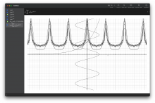
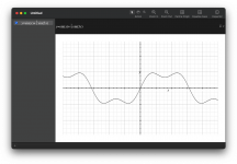
So centre shows a sine wave (actually 4x so that it's fast). I've then created a simple e^x valve function as a mapping. Then applied the that and you can see the output of the spoof valve as the asymmetric waveform.
Super imposed on that waveform is the 3,5,7,9,10 and 20th odd harmonic that makes up the output wave.
Distortion cancelling SET 300B in Sound Practices Fall 1994
Elliano, Brennerman and Bennett published their single ended 300B no-global-negative-feedback design in Sound Practices (Fall 1994). The 300B was driven by an RC coupled Kimmel mu stage. The driver triode was the 6AQ8 (ECC85), with a 12HG7 serving as the mu stage pentode.
With the 6AQ8, measured distortion at 7 Watts was less than 1% from 30Hz to 20kHz - distortion cancellation in action. Distortion was higher when the 6AQ8 was replaced by the 12BH7 or the 12AU7. Might be worth trying in SPICE?
And was it the Wellborne Labs "Laurel" that used a similar design, a 6SL7/6AG7 Kimmel mu stage RC coupled to a 300B? Don't however recall seeing distortion measurements for it ...
So.. on this..
I've got past the mental block of a single wave that is made up of N components (f+harmonics). I now think of the wave as N waves containing a set of H1 through Hinf.
Next I can see the first derivative of the valve function is the rate of change at that point, the second derivative gives the curvature of the wave function at that point.
I can see that an input into a valve is a set of all the frequencies in parallel but physical reality means that is summed. Mathematically, we can apply the valve function to each of the frequencies in the input set but in reality the we're rate limited (in total energy transfer rate) and even impedance delayed thus the output set becomes distorted from the original set. This I assume would explain a little in why a high B+ would result in less distortion - there is more rate of change energy (slew rate) available.
A non-symetrical transfer - you get a set of waves resulting that make up the available transfer rate of energy at that point of time. Hence if the input set causes a rise time that cannot be matched, there is a changing of the set of waves on the output to match the energy. That change is labeled 'distortion'.
I think the next step is for me to work out why for a given energy what dictates the levels of harmonics. I would assume nature's way of finding the lowest power means the wave frequencies that can absorb the most energy from the transfer, at that point in time, is what becomes dominant in the set of frequencies.
Thus if the energy is matches H2 perfectly you will get a large H2, however if the energy matches H3 etc you get that.. If an energy is matched by being spread over 0.5H2 + 0.4H3 then those would essentially get the energy first.. leaving less for the other frequencies. Akin to filling an energy hole with the larger energy rocks first that fit before you start using smaller energy rocks to fill the remaining gaps.
There's obviously a strong correlation that occurs with asymmetric and even multiples compared to the opposite being true for symmetric and odd multiples. Just my hypothesis that this may be because H1 and Hodd correlate when symmetrical, so I suppose I better go and have a read up 🙂
I suspect this has strong links with quantum wave functions and harmonics within those: Quantum harmonic oscillator - Wikipedia wouldn't surprise me if that's related to entropy resulting in stable states. However I'll leave it to say 'energy' and be done with it. (if you read up on low QHO states and using quantum maths you can work out the states and thus the constituent frequencies).
Last edited:
A 6AQ8 is similar to a 12AT7.
A 6AQ8 is very different than either the 12AU7 or 12BH7.
That is why the distortion cancellation of the driver/300B combination was no longer there.
Remember, the 2nd harmonic distortion cancellation is maximum (best cancellation) at only one load impedance, with a real resistance, RL.
That gives a single load line (as in a load resistor on the secondary at mid frequencies).
The combination of the output transformer impedance versus frequency and loudspeaker impedance versus frequency is Not a constant load to the output tube.
Depending on the frequency, the load line is at different slopes (different R),
and at some frequencies the load "line" is elliptical.
At different frequencies, the elliptical load can be different dimensions (width and height, and different 'slopes').
Just my 2 cents (or when I was in the Philippines, my 2 Centavos).
Last edited:
Page 21 of that BBC manual on tubes has a great piece explaining tubes and capacitive/inductance loads resulting in the elliptical load line that 6a3summer is referring to.
A 6AQ8 is similar to a 12AT7.
Yep - main difference being 6AQ8 (ECC85) was developed for the front end of FM receivers. Had lots of screening between the two triode sections and thus about about one tenth the inter-electrode capacitance of the 12AT7 (ECC81). Not such a big deal for audio - might be worth giving the 12AT7 a try.
A 6AQ8 is very different than either the 12AU7 or 12BH7.
That is why the distortion cancellation of the driver/300B combination was no longer there.
Yep, probably goes a long way toward explaining the results. 6AQ8 + 300B = happy times
This is exactly what I have found; a simple resistor anode load on a 6SL7, using a source follower to couple to a 300B, performs much better in terms of overall distortion than anything else. However, if one just looks at the driver stage alone then a mu-follower loaded 6SL7 performs the best by far.Hi All,
I am trying to come up to speed with tube/valve design techniques, particularly zero feedback SET amps. To do this I am investigating circuit behavior and operating points with LTSpice. Let me state upfront that I recognise SPICE is not the be all and end all, but as a tube noob it's the best I have without spending anything.
I would like to make a zero feedback SET 300B amp with the best distortion performance possible for the least circuitry. I am ok with that including a buffer stage, either cathode or source follower. I'm also ok with the odd solid state part here and there if needed.
I see lots designs on the web using a CCS or cascode front end, some with a subsequent buffer, some driving the 300B directly. I appreciate that these input topologies provide more gain and/or PSRR. However, my spice simulations sugggest that these are inferior to a simple resistor loaded common cathode input coupled to a buffer stage (for distortion at least). It seems that while a CCS or cascode may improve the distortion of the input stage, it does not improve overall distortion as the output stage distortion is not cancelled.
This leads me to the conclusion that a good topology is a simple resistor loaded common cathode input coupled to a buffer stage, either cathode or source follower. Since there is no CCS, the input tube must be high gain and the power supply well filtered. Maybe a 6SL7.
Is this how it plays out in practice or:
1) Am I kidding myself thinking that I can get enough voltage swing from a simple resistor loaded 6SL7 to drive a 300B, using say a 2V RMS source? This would be coupled to a source or cathode follower to provide the current needed to properly drive the 300B.
2) Does the distortion cancellation work as well as the simulations suggest, or should we really be trying to minimise distortion in the input stage using a CCS, cascode, etc?
Any thoughts would be appreciated!
Greg
I'm really not sure why this should be - did you ever come to a conclusion on this?
Back in the 50s EMI came up with a microphone preamp that used a distortion cancelling technique. The first stage was an EF86 pentode followed by an ECC88 CC stage with the triodes paralleled. There was local feedback around the output stage. There is also global NFB.
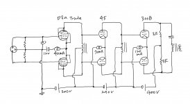
redd 47 schemo
Cheers
Ian
redd 47 schemo
Cheers
Ian
Sakuma?Driving same with same has been done extencively by some Japanese designer...
Hi 6A3sUMMER,A dual triode input stage with coupled cathodes and a CCS in the parallel cathodes . . . that creates an extremely low 2nd harmonic distortion phase inverter. If necessary use another dual triode stage for the driver (if you need the extra gain and/or voltage swing), and drive the push pull output stage.
And I like the sound of those amplifiers too.
Just my opinions; just my experience
I happened to have built an amplifier that matches what you are saying. The final stage is resistor-loaded para feed, giving a lot of heat.
It's all SMPS-powered including heaters and Lundahl transformers, a result of experimental DIY using my ears for many months.
And I also like the sound of this amplifier. 🙂
Attachments
Last edited:
Hi all,
I thought I would plug Stephe's video and channel in general here. It is such an awesome, albeit unplanned demonstration of the principles discussed in this thread.
In the below video, she has a single ended one tube preamp and drives a single ended one tube power amp. She then modifies the preamp for lower distortion and ends up with greater overall distortion at the load. Turns out the preamp with high distortion has lower overall THD at the load. Distortion cancellation in action!
Great to follow her journey as she organically stumbles across this realisation and confirms what I have seen over and over in simulation.
Unfortunately as 6a3summer mentioned, the performance into real speakers might be different, but it's a cool demonstration of the concept nonetheless.
Last edited:
- Home
- Amplifiers
- Tubes / Valves
- Distortion Cancellation and Input Stage Topology


