Hi All,
I am trying to come up to speed with tube/valve design techniques, particularly zero feedback SET amps. To do this I am investigating circuit behavior and operating points with LTSpice. Let me state upfront that I recognise SPICE is not the be all and end all, but as a tube noob it's the best I have without spending anything.
I would like to make a zero feedback SET 300B amp with the best distortion performance possible for the least circuitry. I am ok with that including a buffer stage, either cathode or source follower. I'm also ok with the odd solid state part here and there if needed.
I see lots designs on the web using a CCS or cascode front end, some with a subsequent buffer, some driving the 300B directly. I appreciate that these input topologies provide more gain and/or PSRR. However, my spice simulations sugggest that these are inferior to a simple resistor loaded common cathode input coupled to a buffer stage (for distortion at least). It seems that while a CCS or cascode may improve the distortion of the input stage, it does not improve overall distortion as the output stage distortion is not cancelled.
This leads me to the conclusion that a good topology is a simple resistor loaded common cathode input coupled to a buffer stage, either cathode or source follower. Since there is no CCS, the input tube must be high gain and the power supply well filtered. Maybe a 6SL7.
Is this how it plays out in practice or:
1) Am I kidding myself thinking that I can get enough voltage swing from a simple resistor loaded 6SL7 to drive a 300B, using say a 2V RMS source? This would be coupled to a source or cathode follower to provide the current needed to properly drive the 300B.
2) Does the distortion cancellation work as well as the simulations suggest, or should we really be trying to minimise distortion in the input stage using a CCS, cascode, etc?
Any thoughts would be appreciated!
Greg
Last edited:
The conventional wisdom has long been that the higher the harmonic, the more annoying it is. A widely accepted rule of thumb is that the distortion at full power should fall monotonically with order - i.e 3rd less than second, 4th less than 3rd, etc. Distortion cancellation cancels even orders while increasing odd orders, so it does not meet that rule.
Cascaded stages pump distortion energy into higher harmonics, as does feedback. So to get the desired distortion spectrum most easily, use a single-ended triode as the dominant source, and minimize all other distortions - typically, either a very linear driver with a triode output stage, or a triode driver with a very low distortion output stage.
These are thought to be the reasons for single-ended, triodes, without feedback - and the reasons that they sound different.
Of course there is continuing debate on the accuracy of these conventions, and psychoacoustics has a long way to go before it can offer unequivocal answers! Nevertheless, an amp as described above is a good place to start if you want to hear the difference that people talk about.
There's one main brain obstacle that needs overcoming - the use of power rails carrying signal and the intentional feedback through to cancel. Broskie's Akido is a little more than just PSRR. When you think that a a signal is also fed back, especially with differential amps. It's ideological that your DC power rail never contains signal. Positioning of decoupling caps, filtering or regulators in the power supply allows to reduce.
In terms of simplicity - I think it depends.
A resistor input into a cathode does work - Broskie has several articles on schematics doing this. What you have done is directly connected the current through the valve, thus the value is acting as a common grid amplifier. The buffer then provides the impedance matching and current drive for the 300B?
With cathode input it's become a current input without the distortion of the V-I that the input tube makes. Interesting point on the higher harmonics - https://www.firstwatt.com/pdf/art_cas_amp.pdf
Given a common grid is going to be susceptible to variations in power supplies and including amp signal leakage, I would suggest also considering looking at that and the effect of power supply droop with the operating point.
Last edited:
GregH2,
Do you think that a 2 stage 300B amplifier, can cancel the 2nd harmonic distortion of the input stage, with the 2nd harmonic distortion of the 300B?
(serial stage 2nd harmonic distortion cancellation).
That can be true. It can be arranged that way.
However, it only works into a constant load impedance, RL, on the 300B plate.
The 2nd harmonic distortion of the 300B is dependent on the output transformer's primary impedance at mid frequencies, and also the inductive reactance at low frequencies, and the distributed capacitance at high frequencies (if the capacitance is large enough to be significant), and the leakage reactance from the primary to the secondary).
All these factors determine the effective primary winding RL of the output transformer,, versus frequency when there is a proper resistor load on the secondary.
But then, consider the additional impedance factors at the output transformers secondary . . . the average loudspeaker.
Its impedance varies widely versus frequency, resistive, capacitive, inductive, and a combination (resonant). The numeric impedance, whether pure resistive, or reactive, can vary widely too.
That means the loudspeaker reflects a wide range of impedances to the output transformer
primary, and so the load line, RL of the 300B varies (often not a line, but an ellipse).
The varying load on the 300B plate changes its 2nd harmonic distortion.
That no longer cancels with the input/driver stage's 2nd harmonic distortion.
Consider making the first stage as linear as possible.
Consider trading off power output to get better 300B plate control of the output transformer's primary varying impedance.
A 300B plate impedance of 700 Ohms can control a 3.5k or 5k primary better than a 2.5k primary.
The 3.5k and 5k primaries will also give a better damping factor, to control the speaker better.
Just my opinions.
Last edited:
Thanks for the responses all, the insight is appreciated.
I hadn't considered that the distortion cancellation probably only really works into a resistive load. I'll keep pursuing the more linear input options.
And 6A3Summer I will be sure to use a 5K transfomer! Unfortunately the only viable option around here is a Hammond which don't seem particularly highly regarded on these forums, but it will have to do.
Driving same with same has been done extencively by some Japanese designer, I cannot remember his name at the moment. The intention is to drive the output tube with same but opposite distortions, for cancellation. So you are into something. But isnt the 300B so linear it kinda is overkill, or may even crate more problems than driving it with a very low thd driver?
I have some 6AS7s and use them in a few amplifiers. They are quite curvy, producing some 2nd H. So I tried driving the 6AS7 output with a 6AS7, intending the first 6AS7s 2ndH cancel the output 6AS7's 2nd. And it does work.
I have another amp build going on where I intend to drive a 6V6 with a 6G6 b/c they have similar gain and I hope rather similar behaviour and therefore perhaps the 6G6 will feed the 6V6 with equal but opposite 2nd and the result be better than driving 6V6 with say a 6922, 6SN7, or 12AX7.
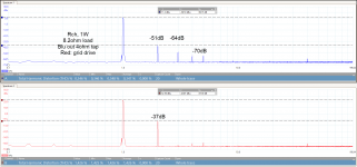
The picture shows the FFT of the 6AS7 output at 1W and the driver 'grid drive' signal. The driver shows the massive 2nd inherent in these tubes, and the output where this has been cancelled to some degree. As much as we can fault the 6AS7, look at the very nice FFT above the 2nd H, very little higher harmonics. The amplitude on the drive signal is about 100Vpp. The output has some higher Hs but that is pretty normal for a zero feedback amp.
I have some 6AS7s and use them in a few amplifiers. They are quite curvy, producing some 2nd H. So I tried driving the 6AS7 output with a 6AS7, intending the first 6AS7s 2ndH cancel the output 6AS7's 2nd. And it does work.
I have another amp build going on where I intend to drive a 6V6 with a 6G6 b/c they have similar gain and I hope rather similar behaviour and therefore perhaps the 6G6 will feed the 6V6 with equal but opposite 2nd and the result be better than driving 6V6 with say a 6922, 6SN7, or 12AX7.
The picture shows the FFT of the 6AS7 output at 1W and the driver 'grid drive' signal. The driver shows the massive 2nd inherent in these tubes, and the output where this has been cancelled to some degree. As much as we can fault the 6AS7, look at the very nice FFT above the 2nd H, very little higher harmonics. The amplitude on the drive signal is about 100Vpp. The output has some higher Hs but that is pretty normal for a zero feedback amp.
Attachments
Last edited:
I missed 6A3sUMMER's post. Intersting and probably correct. But with a rather 'curvy' tube, such as 6AS7, where the 2ndH is so profound, I think there i something to the active cancellation by using same driving same topology.
Tubes that are very linear like 300B etc it probably is pointless or even counterproductive.
Tubes that are very linear like 300B etc it probably is pointless or even counterproductive.
I worked with distortion canceling using 6P41S and 6J9P amp design years ago.
One issue I found was that while simulations showed it worked, in the real world it was very bias-point dependent. In addition it varied greatly from one tube to the next. One has to bias the circuit for a specific set of tubes and it drifts over time, so you have to be rebiasing it regularly.
Looks good on paper, just not worth the effort.
Starting at post 36 here there is a discussion of harmonic cancellation.
Closed loop stability help needed.
Closed loop stability help needed.
I worked with distortion canceling using 6P41S and 6J9P amp design years ago.
One issue I found was that while simulations showed it worked, in the real world it was very bias-point dependent. In addition it varied greatly from one tube to the next. One has to bias the circuit for a specific set of tubes and it drifts over time, so you have to be rebiasing it regularly.
Looks good on paper, just not worth the effort.
Not just the tubes but also the rest of the circuit, caps, resistors etc.
It's ideological that your DC power rail never contains signal.
Since this is intended for a single ended amplifier, then unless the tubes are deliberately arranged with operating points that compliment each other, it is inevitable that the signal loop passes through the last B+ smoothing capacitor via the power rail.
One way to largely negate that is to have the power tube drive a cathode follower (using a matched tube of the same type) at exactly the same operating point. As the power tube multiplies and inverts the signal, it is non-linear in one direction, then that distortion is backed out by the cathode follower which is equally non-linear to the inverted signal, i.e. they want to sit on the same operating point and loadline as each other.
To make sure no signal is on the B+ line, you'd then have to run push-pull, not single ended. If you draw a diagram of where the current comes from and goes to, you'll see it recirculates around the output stage only in a figure of eight if the valves are matched. Put another way, the power supply only supplies constant current if the amp stays in class A. It's sole input on the "noise" is that of recharging the ripple current - it supplies constant current only. A bias servo for the valves will ensure the four operating points stay fixed relative to each other.
To then make sure this push-pull amp is truly independent of the DC power rail fluctuation, you need to organise the input stage and phase inverter to have complimentary operating points such that as the input draws current, the phase inverter uses less current by the same amount. Again, if the two valves run from the same power spur, then they will run at constant current as a pair and power supply has no influence on sound as the current only recirculates around the two valves. For a worked example of this, see the ECC83 input stage of Norman Koren's TENA amplifier. This also contains a bias servo example for his 6550 output stage. Broskie documented the cathode follower operating point cancelling trick on a 300b in a very old Glass Audio article a long way down on his website.
Most people who draw a schematic don't draw the power supply. This means they don't even notice that they are constantly charging and discharging the final PSU capacitor with signal.
In any case, cancelling all of the distortion may not be what you want to do.
kind regards
Marek
Thread Readers:
How far down do you want the B+ variations of a Class A1 Single ended amplifier be?
60 dB, 80 dB, 120 dB?
. . . I am talking about the output tube B+, versus the driver B+, and earlier stage(s) B+.
Either use lots of capacitance on the output tube B+, and large resistors and large capacitances for the next two RC B+ filters. And pay special attention to the negative side ground loops in the B+ supply.
Or, use regulated B+ supplies.
In either case, you have fully taken care of the B+ variations of the output stage, it will not get into the earlier stages.
Just one of many ways to take care of that "problem".
Last edited:
Thread Readers,
Paul Joppa, as always, raises some very interesting points.
Good Job, Paul.
After all that, ask your self:
Why do I want to build a Single Ended Amplifier?
I want dominant 2nd harmonic distortion, and I want the higher harmonics falling off naturally?
I want simplicity of circuit topology?
I have built such circuits, both with DHT, and with Triode Wired Pentode/Beam Power tubes.
I like the sound of them.
Why would I give up that simplicity, by adding compensation circuits, negative feedback, and more? I usually do not do that (although I did try schade and output plate to driver cathode negative feedback modes).
Why do you want to cancel the 2nd harmonic distortion?
If you do that, push pull works.
I built push pull amplifiers, it cancels the 2nd harmonic, even without compensation circuits, negative feedback, etc.
A dual triode input stage with coupled cathodes and a CCS in the parallel cathodes . . . that creates an extremely low 2nd harmonic distortion phase inverter. If necessary use another dual triode stage for the driver (if you need the extra gain and/or voltage swing), and drive the push pull output stage.
And I like the sound of those amplifiers too.
Just my opinions; just my experience
P.S. Cancelling the 3rd harmonic distortion without using negative feedback is a difficult thing to do.
Just another opinion of mine.
(I have built push pull amplifiers where the 3rd harmonic distortion is lower than the 2nd harmonic distortion).
Last edited:
However, it only works into a constant load impedance, RL, on the 300B plate
On that - my understanding is that the output impedance seen by the speaker is the Ra through the transformer (or the transformer as the load) and similarly the Ra load seen by the output tube is actually the speaker impedance through the transformer itself. Hence will vary between speaker to speaker and over the frequency range. Is that correct? (sorry I'm coming from OTL learnings).
My understand of H3 is that being symmetrical, it can be caused by local input grid feedback of the signal+H2. Is that correct?
I've been reading up specifically on odd harmonics perhaps as an addition to the discussion.
H5, 7, 11, 13 etc are odd harmonics
H3, 9, 15 etc are special odd harmonics - Triplen harmonics.
I was wondering about using three phases. It appears that in power systems triplen harmonics in a three phase star supply result in only the triplen harmonic remaining (even the the fundamental is canceled).
Now could you use that in a local feedback? For example superimposing the triplen harmonics onto the common grid of the cascode for a single ended triple amp? Using caps to create a set of phase shifts?
Something like this:
However, it only works into a constant load impedance...
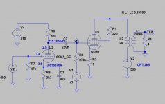
Distortion cancellation seems to work with varying load as well.
Attached circuit has triode connected GU50, which produces alone very "sweet" 10 % THD, mainly 2nd harmonic.
When combined properly biased 6GK5 the THD at optimum 8 ohms load is just 1.6%, but then 3rd harmonic will dominate.
With 16 ohms load THD is 3%, 2nd harmonic dominating and with 4 ohms THD is 6.8%, 2nd harmonic dominating.
Attachments
NickKuck,
Yes, the varying loudspeaker impedance does reflect back through the output transformer, from the secondary to the primary.
I am sorry, I said it this way . . . "However, it only works into a constant load impedance, RL, on the 300B plate".
I should have been more clear on what I meant.
What I should have said is:
"However, that kind of serial stage's 2nd harmonic distortion cancellation only works into a constant load impedance, RL, on the 300B plate.
That is because, when the driver 2nd H. distortion is equal to the 300B 2nd H. distortion, the cancellation is complete . . .
But when RL varies (because of loudspeaker varying impedance versus frequency), the 300B 2nd H. distortion varies along with the loudspeaker varying impedance.
That means the cancellation is no longer complete, because the two distortions are no longer equal.
Example: A SE 300B with a 3k Ohm primary impedance, and an 8 Ohm secondary.
A typical two way "8 Ohm" rated loudspeaker may have a minimum impedance of 4 Ohms at 2 frequencies, and a 16 Ohm maximum impedance at 2 other frequencies.
That means the 300B load lines vary from 1.5k to 6k Ohms.
Draw 3 load lines on a 300B family of curves, RL of 1.5k, 3k, and 6k Ohms.
Look at the varying 2nd harmonic distortion versus the different load lines.
Resistive loudspeaker impedances are straight lines.
But at many frequencies, the loudspeaker impedance is reactive, not resistive (has either an inductive reactance, or a capacitive reactance).
Those load lines are not straight lines, they are Ellipses. That causes another level of distortion.
When the inductive reactance and capacitive reactance are both present, but are equal, the load line is resistive
(again, a straight load line).
In short, with a widely varying load line, varying resistive, varying reactive, the % of 2nd harmonic distortion will be varying.
The driver % of 2nd harmonic distortion does not vary versus the loudspeaker load impedance.
So, the 2nd harmonic distortion cancellation is not always complete; (at every frequency when the driver 2nd H. D. does not equal the 300B 2nd H. D).
I hope that makes it clear.
Last edited:
NickKuck,
I am sorry, I said it this way . . . "However, it only works into a constant load impedance, RL, on the 300B plate".
I should have been more clear on what I meant.
What I should have said is:
"However, that kind of serial stage's 2nd harmonic distortion cancellation only works into a constant load impedance, RL, on the 300B plate.
That is because, when the driver 2nd H. distortion is equal to the 300B 2nd H. distortion, the cancellation is complete . . .
But when RL varies (because of loudspeaker varying impedance versus frequency), the 300B 2nd H. distortion varies along with the loudspeaker varying impedance.
That causes the cancellation to be no longer complete, because the two distortions are no longer equal.
I hope that makes it clear.
Thank you that makes sense. Sorry I wasn't trying to be pedantic, just inquisitive.
Last edited:
NickKuk,
In regards to your study of Odd (and Even) Harmonic distortion:
(Good for you . . . studying).
Here is something you may find interesting:
2nd Harmonic distortion from an amplifier:
A sine wave that is distorted to have more amplitude in one direction (one alternation) than the other direction (the opposite alternation).
The fundamental and 2nd harmonic are present.
3rd Harmonic distortion from an amplifier:
A sine wave that is distorted (symmetrically compressed amplitudes) in both directions of alternations.
If that sine wave is clipped symmetrically to the limits, it becomes a square wave.
A square wave has the fundamental, and All the odd harmonics (limited to frequencies as far as the rise and fall times limit the top bandwidth).
An interesting case of amplifier distortion (sometimes forgotten or overlooked):
If the sine wave is completely clipped, but one alternation has more time than the other alternation (40% versus 50% for example), then . . .
The fundamental is present,
All the Odd harmonics are present,
And . . .
All the Even harmonics are present.
. . . (Well, again, the top Odd Harmonic distortion frequencies, and top Even Harmonic distortion frequencies are limited by the rise and fall times, which limits the bandwidth of the harmonics).
- Home
- Amplifiers
- Tubes / Valves
- Distortion Cancellation and Input Stage Topology