how about giving "engineers" a little credit?
its sad to see that Nelson's very good measurement paper with excellent points about device selection and optimum biasing is spoiled by an "anti-negative feedback" tone - when Nelson should understand the literature and facts of negative feedback very well and be able to give a better "fair and balanced " version than expected from Fox News
he even choose to repeat the "degeneration is not the same as negative feedback" nonsense in a follow up post
but in the Negative Feedback thread he did come to recognize that his data was simply not sufficient to support the erroneous distinction:
now (2011 - I checked the calendar) we have another naive "no feedback" paper that references the uA741 op amp in support of their position
It is painful for an engineer to read the posts about the supposed over simplistic test signals, measurements by “cloth eared”, “meter reading” engineers posted largely by computer modem Mbaud ADSL links only enabled by the last decade’s advances in analog op amp design and fabrication processes needed to provide sufficiently low (IM) distortion at 100KHz-MHz in high feedback transmit and receive circuits for the 16-64 frequency QAM 16 (or more level) carrier over thousands of feet of (sometimes 50+ year old) twisted pair designed/installed for baseband telephone quality audio signals – readers/writers of audiophile mags really think we “know nothing” about complex signals, feedback?
Is the public really that clueless about technology?
there are many reasonable disagreements/unknowns about audio perception, why we accept/like any particular recording/playback technology
there are many fewer about electrical signals and amplification:
for some conditions and fairly simple math reguarding the specific subject of negative feedback and distrotion interaction in audio amplifiers the Cherry reference is really the minimum level of reading required to intelligently debate the subject
its sad to see that Nelson's very good measurement paper with excellent points about device selection and optimum biasing is spoiled by an "anti-negative feedback" tone - when Nelson should understand the literature and facts of negative feedback very well and be able to give a better "fair and balanced " version than expected from Fox News
he even choose to repeat the "degeneration is not the same as negative feedback" nonsense in a follow up post
but in the Negative Feedback thread he did come to recognize that his data was simply not sufficient to support the erroneous distinction:
Yes, it is very nice work.
It gives an explanation for my failure to see this phenomenon in
degenerated JFETs down to .001%. The higher order harmonics
appear to go down as the square of the open loop distortion figure.
I'll just have to drive those poor little JFETs harder...
😎
now (2011 - I checked the calendar) we have another naive "no feedback" paper that references the uA741 op amp in support of their position
It is painful for an engineer to read the posts about the supposed over simplistic test signals, measurements by “cloth eared”, “meter reading” engineers posted largely by computer modem Mbaud ADSL links only enabled by the last decade’s advances in analog op amp design and fabrication processes needed to provide sufficiently low (IM) distortion at 100KHz-MHz in high feedback transmit and receive circuits for the 16-64 frequency QAM 16 (or more level) carrier over thousands of feet of (sometimes 50+ year old) twisted pair designed/installed for baseband telephone quality audio signals – readers/writers of audiophile mags really think we “know nothing” about complex signals, feedback?
Is the public really that clueless about technology?
there are many reasonable disagreements/unknowns about audio perception, why we accept/like any particular recording/playback technology
there are many fewer about electrical signals and amplification:
there's no "conflicting opinion" among text book writers, accredited university EE teaching on the subject - only Curl, Hansen, Audiophile magazine writers, other people trying to "sell" the "no feedback" concept make any distinction between degeneration, followers and negative feedback in general - Blackman's theorem, gain stabilization, distortion reduction, high frequency stability issues all apply to "local" as well as "global" feedback circuits
in particular the infamous "harmonic multiplication" character of negative feedback works to create the "bad" higher order harmonics when even "good" degeneration or follower circuits are used with perfect "square law" gain devices
the sim modifies my http://www.diyaudio.com/forums/soli...mately-driver-sound-quality-7.html#post920583 post
if you like fine checks of theory the 8.5/.4 input signal amplitude ratio between the open loop common source and "follower" configurations in the sim (~= feedback loop gain difference) very closely explains the 27 dB reduction in the 2nd order harmonic - and of course you can see the follower's higher harmonics in yellow vs the green open loop gain stage
further discussion has occured in some Cordell interview threads, "Baxandall" is a keyword due to his Wireless World article
for some conditions and fairly simple math reguarding the specific subject of negative feedback and distrotion interaction in audio amplifiers the Cherry reference is really the minimum level of reading required to intelligently debate the subject
we've beat the subject to death in the Cordell negative feedback thread
Baxandall (and others before and after) have done the negative feedback "harmonic growth" math - among the the conclusions:
that it is worst at ~ 10-15 dB feedback
it doesn't depend on wether the feedback is "global" or local" - it can be seen with degeneration too
just use lots of negative feedback once youv'e started using any at all and above ~40 dB of feedback all harmonic distortion orders are reduced, and they assume the decreasing level as order increases pattern so many claim is important
higher order compensation, fast output devices allow up to 60 dB loop gain in audio power amps at 20 KHz so all conventional "audio" signals can benefit from high feedback factor distortion reduction
not directly related but Otala's TIM concerns can be addressed in input, VAS, compensation design and Is Not made worse by high negative feedback factor - or even a sloping feedback factor in the audio band - the "flat open loop bandwidth over the audio range" prescription is simply wrong on TIM grounds
(although Bode's maximal feedback design does use flat feedback factor over the working band to boost the bandwidth benefiting from high feedback factor by an octave)
I think Cherry did the best feedback "distortion growth" math job in:
Cherry, “Estimates of Nonlinear Distortion in Feedback Amplifiers” JAES V48#4 2000
a bad use of high feedback is to try to "fix" a bad amplifier design with static or dynamic underbiased output devices which show deadbands with expected loads and V,I slewing requirements
build linear stages with generous bias that can handle the required real world loads, signals with only smooth nonlinearities and there is no indication that high negative feedback does anything except improve the amp's linearity at the usual and quite controllable cost in frequency compensation for stability
actually while the situation is complex "global feedback" with high excess loop gain is easily shown to reduce distortion and frequency response variations due to the gain stage imperfections much more strongly than any partitioning of local feedback around the same gain stages
within some limits you should also be able to obtain the same stability, output impedance with only global feedback
local feedback may simplify circuit design by reducing interaction between circuit blocks, and can improve nonlinear stability/overload recovery which is probably why the most popular amp circuits use a mix of local and global feedback
while respecting their circuit design prowess I find most "no global feedback" or "low feedback is a barely acceptable evil" proponents profoundly ignore/misrepresent feedback theory and resist Cambrell, Cordell, Vanderkooy and Lipshitz and Cherry's works that contradict their prejudices
when the supposed evils of high global feedback in audio amplifiers have been reduced to concrete, testable hypothesis the cited authors have convincingly shown there is little or no substance to the most common complaints or that adjustments to forestall say “slew rate induced distortion” may be incorporated in high gain global feedback amplifiers without need to adopt “no feedback” topologies to fix the purported problems
feedback cannot “fix” bad amplifiers- the open loop gain stages must be able to power the load without deadbands, hysterisis, clipping, current limiting either static or dynamic – once these conditions are obtained then (global) negative feedback can reduce smooth nonlinearities and stabilize frequency response, gain with respect to device and operating point variations in the frequency range where the excess loop gain can be large – with modern devices and advanced loop gain compensation it isn’t a huge challenge to have 60 dB loop gain at 20KHz
it is a major disservice to the audio community that popular magazines, advertorials, and “just listen” naive subjectivism ignoring known psychoacoustics and perceptual testing realities make the above the least bit controversial or dismissible as "only an alternative opinion"
Last edited:
A few friendly remarks:
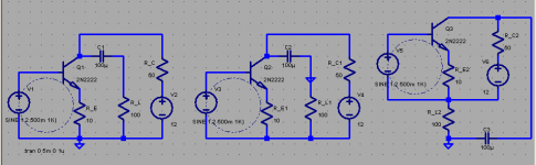
From p. 5 re: two transistor circuits:
<<there is another method for amplifier linearization, the literature erroneously
referred to as feedback. The picture above shows two functional identical
amplifier stages. The left amplifier stage is working with a negative feedback
loop, whereas the right one is linearized through a resistor in the emitter line.>>
Since when did good engineering textbooks become "erroneous literature"?
Left amp has "Neg. Voltage FB",
Right amp has "Neg. Current FB"
It is in the books.
<<...we have found that negative feedback reduces the output resistance. This
holds true for the left circuit part, but not for right part. The larger the emitter
resistance gets, the more linear the circuit and the larger the output resistance>>
Neg voltage FB reduces the output resistance, neg. current FB increases Rout.
From p. 12:
<<This insight has motivated us to ... use carefully designed amplifying stages
without any kind of negative feedback instead. As demonstrated on page 5
and following, measures for linearization and stabilization are necessary. These
measures, however, are not negative feedback loops. The term "zero feedback
amplifier" for LINNENBERG AUDIO gear is therefore correct and admissible.>>
Clearly, these statements about absence of any kind of NFB (in your gear) need
to be revised.
Overall, this white paper is written not in a very good literary style: jumping from
something to something, and not with very convincing logic. Language translation issue?
The subject of distortion harmonics, generated by NFB, was covered by P. Baxandall long ago, and very well, and can be referenced.
Last edited:
Thank you very much for the response
Thank you very much for the response.
The paper was written for absolute beginners as well as for someone with a bit more elaborate interest in audio. It should read in two languages, cover a lot of topics with some eye openers and should not exceed the 13 pages. This was difficult to achieve. If you feel, that it "is written not in a very good literary style: jumping from something to something, and not with very convincing logic", I apologize for that. There was simply no space for detailed explanation and argumentation. A customer for an audio product will never read textbooks; he is pleased to know a tiny little bit more about his amplifier / CD-player or what so ever.
I do not apologize for the content and there is nothing to be revised. The whole feedback yes / no issue has been discussed here in this forum and else where to death. I made my point on the current feedback issue, which is not a classic feedback for me. I know that textbooks like “Halbleiterschaltungstechnik” from the honourable authors Tietze + Schenk (the book is nearly a bible for German students) call it “current feedback”. Perhaps someone can show me the loop, can show me where the output signal is measured / probed for a correction loop.
In my perception it would be much more accurate to call this a) linearization or if someone wishes b) bootstrapping technique.
a) Every active device has a current specific transconductance gm, which is as we all know extremely nonlinear. The reciprocal of gm is a resistance, still nonlinear of course. By connecting a much larger resistor in series with the internal resistance we achieve linearization of the resulting gm'.
b) All circuit potentials change directly in dependence of one and the same collector current, bootstrapping the emitter and holding thus a change in UBE very small.
I think it doesn’t make much sense to answer jcx, it seems like he is pleased by quoting himself. Keep cool man.😎
Attachments
Last edited:
I'm cool, expect great entertainment from people leaping to your defense
I can quote your paper then?
“…Unfortunately,
this is only half true: music is a
complicated dynamic action, not
covered by the theory of process and
control engineering.”
I find the “unfortunate” part being that you think you can get away with a bald faced lie in any language
Those having an engineering education and having taken the courses, have worked through the “step response” math included in every introductory Control theory textbook I’ve ever encountered will recognize that your use of the “Authoritative Voice” implies you have been there, done that - and as a consequence your statement is best characterized as a Lie – at worst as Marketing
For the rest who have to weigh the rhetoric on less direct basis I recommend a simple search for books with subject/title keywords: Dynamic System Control
(this is also a rhetorical technique, appeal to (other’s) Authority – you have to make your own judgment on their reliability)
(do I really have to point out that 90+% of commercial music is recorded/produced/distributed in digital formats that can be simplistically characterized as “a series of steps”)
I think my self quotes give the generally accepted engineering understanding of negative feedback theory as encompassing and usefully expanding understanding of degeneration and followers – this is one of the hallmarks of a useful theory – it opens new possibilities while explaining and presenting in the new context practices that predate the theory
Claiming your particular circuits are not/do not use "feedback" is pure Marketing BS
Last edited:
Ila, there is no need to apologise, Source/Cathode/Emitter degeneration is definitely not a feedback - no signal is being "fed back" and there is no loop and no reductive comparison takes place. It's just the way the gain devices are built.
Nelson's measurements confirm big difference between degeneration and feedback loop.
Horowitz is not the only textbook author, there are/were people in this world that really understand the topic.
Best regards!
Nelson's measurements confirm big difference between degeneration and feedback loop.
Horowitz is not the only textbook author, there are/were people in this world that really understand the topic.
Best regards!
how do you say "shooting fish in a barrel" in your language
OK, should I soften my rhetoric to “you’re propagating lies you don’t have the education to understand”?
admittedly highly popular lies the "Audiophile" popular press seems to eat up and delight in regurgitating at the least hint that real engineering understanding/principles might interfere with their highly profitable "story telling"
Try search again: series shunt feedback
Google returns ppt and pdf lectures slides, papers on accepted feedback "taxonomy" - is Prof. Marshall Leach an acceptable “Authority”?
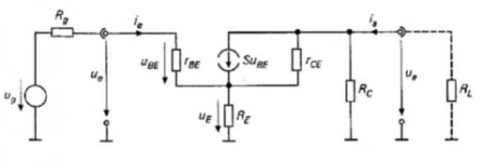
The “not touching/sampling the output” is not a valid objection – controlled current sources have 2 terminals – the “output” from either is the same for analysis - - and remarkably accurate for real world 3-termianl gain devices
Haven’t you seen the analysis trick of moving the gnd? – we can label any one node of a circuit with the gnd symbol without changing the operation in any way
But sometimes the transformation aids understanding by fitting a circuit into a more commonly recognized pattern:
below the circuit topology is identical in all three drawings – the dotted “loop” is the same, but maybe the third picture makes its interpretation as local negative feedback more easily seen
the formal feedback language is that R_E in "series" with the load "samples" the output current, the R_E Voltage drop is subtracted from the Source V by the "series" connection in the Vsource, Qbe, R_E loop
making this a "series-series" feedback circuit
the subject is fairly well represented on the web – even the peer reviewed professional literature
http://www.eecs.berkeley.edu/~bora/publications/ISCAS98-Feedback.pdf
the source LTspice file is attached (just strip the .txt) and you can check measurements by using the "differential" probe feature, click a node with the red color "probe", and hold down the button while moving to the "reference" node, releasing when the black "probe" is on the node - you should see that the component V differences don't care about which node is labeled with the "gnd" triangle
OK, should I soften my rhetoric to “you’re propagating lies you don’t have the education to understand”?
admittedly highly popular lies the "Audiophile" popular press seems to eat up and delight in regurgitating at the least hint that real engineering understanding/principles might interfere with their highly profitable "story telling"
Try search again: series shunt feedback
Google returns ppt and pdf lectures slides, papers on accepted feedback "taxonomy" - is Prof. Marshall Leach an acceptable “Authority”?
The “not touching/sampling the output” is not a valid objection – controlled current sources have 2 terminals – the “output” from either is the same for analysis - - and remarkably accurate for real world 3-termianl gain devices
Haven’t you seen the analysis trick of moving the gnd? – we can label any one node of a circuit with the gnd symbol without changing the operation in any way
But sometimes the transformation aids understanding by fitting a circuit into a more commonly recognized pattern:
below the circuit topology is identical in all three drawings – the dotted “loop” is the same, but maybe the third picture makes its interpretation as local negative feedback more easily seen
the formal feedback language is that R_E in "series" with the load "samples" the output current, the R_E Voltage drop is subtracted from the Source V by the "series" connection in the Vsource, Qbe, R_E loop
making this a "series-series" feedback circuit
the subject is fairly well represented on the web – even the peer reviewed professional literature
http://www.eecs.berkeley.edu/~bora/publications/ISCAS98-Feedback.pdf
the source LTspice file is attached (just strip the .txt) and you can check measurements by using the "differential" probe feature, click a node with the red color "probe", and hold down the button while moving to the "reference" node, releasing when the black "probe" is on the node - you should see that the component V differences don't care about which node is labeled with the "gnd" triangle
Attachments
Last edited:
Ila, there is no need to apologise, Source/Cathode/Emitter degeneration is definitely not a feedback - no signal is being "fed back" and there is no loop and no reductive comparison takes place. [snip]!
There's no need for a visible external loop. The output of an emitter follower is developed across the Re, so the 'effective input signal' becomes Vb-Ve. That is 100% nfb, and that is the reason an emitter follower can only have a theoretical gain of no more than 1, because of the 100% feedback.
Pure, simple and easy to understand nfb.
jan didden
jcx, being rude doesn't help your cause. Please don't discuss my education before you get one.
Your drawings of emitter degeneration don't demonstrate feedback:
voltage on base and emitter are in phase. If there were signal feeding from emitter to base with both voltages being in phase, that would make an oscillator and we know it doesn't.
The thing is much simpler:
control voltage causes the current flow through device and that current developes the voltage across the Re. There is no reaction between two voltages (except for mostly negligible reaction through parasitic capacitances).
jcx, being rude doesn't help your cause. Please don't discuss my education before you get one.
Your drawings of emitter degeneration don't demonstrate feedback:
voltage on base and emitter are in phase. If there were signal feeding from emitter to base with both voltages being in phase, that would make an oscillator and we know it doesn't.
The thing is much simpler:
control voltage causes the current flow through device and that current developes the voltage across the Re. There is no reaction between two voltages (except for mostly negligible reaction through parasitic capacitances).
But of course there is! Without the Re the current trough the device would strongly increase with increasing Vin. With an Re, the voltage across Re subtracts from Vin to make the Vbe and therefor the current cannot increase so strong. max gain is 1 because of 100% nfb.
jan didden
What you say is that control value (Vbe) becomes smaller because of the raise of the emitter potential (caused by voltage drop across Re). That kind of reaction is not a feedback. It's emitter degeneration.
What you say is that control value (Vbe) becomes smaller because of the raise of the emitter potential (caused by voltage drop across Re). That kind of reaction is not a feedback. It's emitter degeneration.
Yes. Same thing, different word. All the concepts, calculations and circuit attrributes resulting from the application of negative feedback are fully in force for an emitter follower. Stability, change in Zout, improved linearity paid for with decreased gain, thermal eqilibrium, just use the well-known nfb calculations and there you are.
jan didden
Juma, Ivo already posted this:
<<I know that textbooks like “Halbleiterschaltungstechnik” from the honourable authors Tietze + Schenk (the book is nearly a bible for German students) call it “current feedback”. >>
so, no need to promote the opposite. Am I correct to read your statement,
<<Horowitz is not the only textbook author, there are/were people in this world that really understand the topic.>>
that Horowitz (and Hill, that makes two of them) do not really understand the topic?
because I just checked p. 84, the paragraph called "Emitter resistor as feedback", right before the paragraph 2.13 in their book.
<<In my perception it would be much more accurate to call this a) linearization...>>
Again, linearization effect is not that simple, Baxandall article:
http://linearaudio.nl/library-1.htm
Juma, if you going to recheck the issue with your sources, look also for the definition of the (source) follower: in your last thread about 25W cl. A, you employ the laterals as Common Source, yes Common Source (with gain), and not as a Common Drain (follower). Yes, I know how many people will try to convince us otherwise, but those, who really want to know, will see this (like I am the first one to say this...).
On the other hand, some people simply do not care to know, and should not be bugged
with all that basic knowledge and should be left in peace.
Yes. Same thing, different word. All the concepts, calculations and circuit attrributes resulting from the application of negative feedback are fully in force for an emitter follower. Stability, change in Zout, improved linearity paid for with decreased gain, thermal eqilibrium, just use the well-known nfb calculations and there you are.
jan didden
We could say degeneration is NFB by just utilising local I to V?
Last edited by a moderator:
(Stepping into territory I am far from qualified to do...)
Isn't that the important point? In your paper I think you are saying that NFB is only Bad because the error is being calculated from a delayed version of the signal. Well, even in the 'degeneration' case, the error calculation of the 'feedback' is affected by stray capacitance and/or inductance, thus meaning increasing errors at high frequencies... Still NFB; still the same problems.
...(except for mostly negligible reaction through parasitic capacitances).
Isn't that the important point? In your paper I think you are saying that NFB is only Bad because the error is being calculated from a delayed version of the signal. Well, even in the 'degeneration' case, the error calculation of the 'feedback' is affected by stray capacitance and/or inductance, thus meaning increasing errors at high frequencies... Still NFB; still the same problems.
We could say degeneration is NFB by just utilising local I to V?
Degeneration is originally a term used in the RF world, but the concept is identical to nfb. The result of your output signal causes the decrease in effective input signal (Vbe) and has all the properties of nfb on the attributes of the amp stage. There really is no difference except in use of words.
jan didden
(Stepping into territory I am far from qualified to do...)
Isn't that the important point? In your paper I think you are saying that NFB is only Bad because the error is being calculated from a delayed version of the signal. Well, even in the 'degeneration' case, the error calculation of the 'feedback' is affected by stray capacitance and/or inductance, thus meaning increasing errors at high frequencies... Still NFB; still the same problems.
There is no delayed reaction. This is a common fallacy. The effective input signal is immediately influenced by the output signal.
(There is a delay in the nS range but that's 1) not what the poster means and 2) not of importance in audio).
Edit: I tried to explain it in one of my blogs, see:
http://www.diyaudio.com/forums/blogs/janneman/454-feedback-how-late-time-same-time-all-time.html
jan didden
Last edited:
Doesn't Common Drain (source follower) still have current gain?
While Common Source with 100% feedback has neither voltage gain or current gain.
If this is correct isn't that a significant difference?
While Common Source with 100% feedback has neither voltage gain or current gain.
If this is correct isn't that a significant difference?
Last edited:
Degeneration is originally a term used in the RF world, but the concept is identical to nfb. The result of your output signal causes the decrease in effective input signal (Vbe) and has all the properties of nfb on the attributes of the amp stage. There really is no difference except in use of words.
jan didden
I think they coined it from the effect it has on reducing gm originally. Like 'degenerating' the amplification potential. Its a tight local linearisation loop for voltage through the conversion of emitter current on the emitter resistor. And works as NFB. Maybe the conceptual idea that NFB is what we create with an external loop is spread enough so it tends to get forgotten that NFB is the mechanism, not the technique. Any automatic gain control is NFB.
I think they coined it from the effect it has on reducing gm originally. Like 'degenerating' the amplification potential. Its a tight local linearisation loop for voltage through the conversion of emitter current on the emitter resistor.
Yes that sounds probable.
jan didden
Doesn't Common Drain (source follower) output still have current gain?
While Common Source with 100% feedback has neither voltage gain or current gain.
If this is correct isn't that a significant difference?
Common source with 100% feedback can have any current gain you want, by chosing your load impedance.
jan didden
- Home
- Amplifiers
- Pass Labs
- Distortion and Negative Feedback