I've got a MOSFET source follower (I use an IRFP044N, but will be replacing that with an IRFP044 when they come on tuesday). And I was wondering how high I could change the input impedance (it's set by the resistor going from input to ground). It's currently at 50k, but I was wondering if it would cause any harm if I changed it to something like 300k or high like that. I ask because I run it from a tube stage that has a low output impedance so the input capacitance of the MOSFET isn't a problem, but I'd like a high input impedance so that I can use a better quality smaller polystyrene cap. I just don't know if this will cause a problem with the high-frequency response of the system...
If you make the coupling capacitor really small, you'll get a capacitive voltage division between the capacitor and the source follower input capacitance. Because the MOSFET capacitance is non-linear, this may result in an increased distortion. Besides, the thermal noise from the DC bias resistor will increase if you increase it and decrease the coupling capacitor accordingly, but I don't think this is going to be a problem in a power amplifier output stage.
You can probably make the Gate resistor 10Megs.
The input capacitance of the MOSFET may be several hundred pF, so you are going to need about the fattest polystyrene cap made if you want to avoid cap-divider loss.
The input capacitance of the MOSFET may be several hundred pF, so you are going to need about the fattest polystyrene cap made if you want to avoid cap-divider loss.
You are contemplating driving some of the most non-linear capacitances you'll find in any circuit and you are worried about using a polystyrene coupling cap. Why not use a polypropylene if you want to be fussy?
Why not use a polypropylene if you want to be fussy?Guys, you forget that the MOSFET's capacitance is _not_ the Cgs (according to datasheet), it's lower and has to do with load and gm. The Cgd is the same as the datasheet.PRR said:You can probably make the Gate resistor 10Megs.
The input capacitance of the MOSFET may be several hundred pF, so you are going to need about the fattest polystyrene cap made if you want to avoid cap-divider loss.
Mosfet input capacitance
Can anyone please explain possibly with maths what happens to a Cgs of 2400pf of an STW34NB20 for example, when configured as source follower in a PP power stage (in AC - bandwidth issue).
Some people say that it's very hard to drive because the 2400pf input capacitance, some people say if gain is near 1 it's bootsrapped so it goes away (so it should be easy to drive) http://www.diybanter.com/electronic-schematics/309241-small-mosfet-input-capacitance.html , some say that it goes to 1/10.
Thanks
2 minutes later... I found this:
http://www.freeclassnotesonline.com/Source-Follower-Amplifier-Capacitance.php
"The input capacitance of a source follower configuration shown in Figure 1 is defined as the sum of the gate to drain capacitance, and gate to source capacitance multiplied by, 1 minus the gate to source gain, so:
Cin = CGD + CGS(1 - AGS)
Where: AGS = RS / RS + (1/gm) if the drain resistance is much greater then the source resistance as is often the case (rd >> RS)."
Guys, you forget that the MOSFET's capacitance is _not_ the Cgs (according to datasheet), it's lower and has to do with load and gm. The Cgd is the same as the datasheet.
Can anyone please explain possibly with maths what happens to a Cgs of 2400pf of an STW34NB20 for example, when configured as source follower in a PP power stage (in AC - bandwidth issue).
Some people say that it's very hard to drive because the 2400pf input capacitance, some people say if gain is near 1 it's bootsrapped so it goes away (so it should be easy to drive) http://www.diybanter.com/electronic-schematics/309241-small-mosfet-input-capacitance.html , some say that it goes to 1/10.
Thanks
2 minutes later... I found this:
http://www.freeclassnotesonline.com/Source-Follower-Amplifier-Capacitance.php
"The input capacitance of a source follower configuration shown in Figure 1 is defined as the sum of the gate to drain capacitance, and gate to source capacitance multiplied by, 1 minus the gate to source gain, so:
Cin = CGD + CGS(1 - AGS)
Where: AGS = RS / RS + (1/gm) if the drain resistance is much greater then the source resistance as is often the case (rd >> RS)."
Last edited:
I consider it a common "error" to use power mosfet with 40 A Id ratings in circuits with mA or single digit A load currents
particularly when I would guess someone driving them with a tube stage was hoping for "square law" gm for similarity to tube characteristics
when used at small fractions of Id the vertical power mosfet gm is quasi-exponential in the "sub-threshold" region of Vgs
and as has been pointed out the excessivly large, nonlinear capacitances become additional distortion sources - even considering Cgs bootstrapping you could have near nF nonlinear input C - 100 Ohms wouldn't be "low impedance drive" - if you want the nonllinear C*Rdrive to be sub 1%
of course since a follower is a 100% local negaitve feedback circuit you will get a complex odd + even, higher order distortion harmonic structure even if the device were working with "square law" gm
a "better quality polystyrene cap" wouldn't be my 1st choice for reducing distortion/improving accuracy
if you need the output amp cappacity of the irfp044 then you likely need another buffer or local feedback gain stage to drive it from a tube circuit without adding significant "solid state" distortion
Last edited:
Charging the Cgs is based on the voltage acrosss the g-s in addition to other things. In a follower circuit, there is very little Vg-s change with signal. Hence you are not charging the capacitance refrenced by the datasheet Cgs value. It is much lower.
Sorry, no math 😉
Sorry, no math 😉
Member
Joined 2009
Paid Member
of course since a follower is a 100% local negaitve feedback circuit you will get a complex odd + even, higher order distrotion harmonic structure even if the device were working with "square law" gm
This is one thing I still read conflicting ideas about - sorry if this is a bit off topic but is the inherent negative feedback of a follower not somehow 'better' than loop feedback ?
there's no "conflicting opinion" among text book writers, acredited university EE teaching on the subject - only Curl, Hansen, Audiophile magazine writers, other people trying to "sell" the "no feedback" concept make any distinction between degeneration, followers and negative feedback in general - Blackman's theorem, gain stabiliztion, distortion reduction, high frequency stability issues all apply to "local" as well as "global" feedback circuits
in particular the infamous "harmonic multiplication" character of negative feedback works to create the "bad" higher order harmonics when even "good" degeneration or follower circuits are used with perfect "square law" gain devices
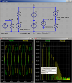
the sim modifies my http://www.diyaudio.com/forums/soli...mately-driver-sound-quality-7.html#post920583 post
if you like fine checks of theory the 8.5/.4 input signal amplitude ratio between the open loop common source and "follower" configurations in the sim (~= feedback loop gain difference) very closely explains the 27 dB reduction in the 2nd order harmonic - and of course you can see the follower's higher harmonics in yellow vs the green open loop gain stage
further discussion has occured in some Cordell interview threads, "Baxandall" is a keyword due to his Wireless World article
in particular the infamous "harmonic multiplication" character of negative feedback works to create the "bad" higher order harmonics when even "good" degeneration or follower circuits are used with perfect "square law" gain devices
the sim modifies my http://www.diyaudio.com/forums/soli...mately-driver-sound-quality-7.html#post920583 post
if you like fine checks of theory the 8.5/.4 input signal amplitude ratio between the open loop common source and "follower" configurations in the sim (~= feedback loop gain difference) very closely explains the 27 dB reduction in the 2nd order harmonic - and of course you can see the follower's higher harmonics in yellow vs the green open loop gain stage
further discussion has occured in some Cordell interview threads, "Baxandall" is a keyword due to his Wireless World article
Attachments
Last edited:
Member
Joined 2009
Paid Member
- Status
- Not open for further replies.
- Home
- Amplifiers
- Solid State
- Changing input impedance of a source follower?