Hi,
I have been building a simple TPA3122D2N based mono class D amp, trying to follow as precisely as possible TI datasheet. PCB has been lay out in Eagle and manufactured be Seeedstudio, soldering has been kind of a hassle (damn you smd component) but in the end it worked! The power supply is a IRM30-12 by meanwell.
Trouble is there seems to be some distorsion on high frequencies. Some really strong harmonics, that can only be heard on the tweetter.
I checked and checked but still the most probable issue is that I made a circuit mistake or badly selected a component.. So I came here for help! I join a PDF of my circuit board with farnell references of component used. By the way, if anyone wants the eagle file, don't hesitate!
Thanks in advance,
Ben
Attachments
In advance, I apologize for my obvious lack of technicality (in addition with the language issue as English is not my native language).
The chip is the tpa3122d2 (http://www.ti.com/lit/ds/symlink/tpa3122d2.pdf), and if that is what you are talking about, the oscillating frequency is caracterised in the datasheet as min 230 typical 250 high 270 kHz
The chip is the tpa3122d2 (http://www.ti.com/lit/ds/symlink/tpa3122d2.pdf), and if that is what you are talking about, the oscillating frequency is caracterised in the datasheet as min 230 typical 250 high 270 kHz
Could be a layout issue. I never experienced that sort of problem with the boards I built around this IC.
Probably not related to your problem, but you do realize that grounding one input and using the outputs in a differential fashion has no advantage other than avoiding the use of output caps? It is not truly "bridged" without inverting the signal on one of the inputs. You are basically just trading more output noise in exchange for not having to use DC blocking caps.
Probably not related to your problem, but you do realize that grounding one input and using the outputs in a differential fashion has no advantage other than avoiding the use of output caps? It is not truly "bridged" without inverting the signal on one of the inputs. You are basically just trading more output noise in exchange for not having to use DC blocking caps.
I'm guessing the problem is indeed related to using the IC that way.
Try output capacitor or real BTL to confirm that's the case? You can think of it as doing it for science.
Try output capacitor or real BTL to confirm that's the case? You can think of it as doing it for science.
I'm guessing the problem is indeed related to using the IC that way.
Well, I experimented with using it that way and I don't remember it having any negative effect other than slightly higher noise, which is why I suggested it might be a layout problem.
I would definitely try to run it as per the datasheet to see if the noise goes away though. Don't need to do anything other than put a cap on the output and reference the load to ground instead of the other channel.
I indeed did not realized that..
I followed as closely as possible TI notice as they never failed me, but I didn't second guess what plus input and minus input meant, I just thought it was to say signal and ground.
I now see that indeed half of the chip is amplifying nothing! I would love to try both option "for science" (though as I don't have any testing equipment, my not-so-scientific ears would be the only judge).
For the version with output cap, [theAnonymous1] made it very clear how to do it. But how do you invert signal in BTL. Sorry if this is an obvious question but I really don't see. An opamp wired as an inverter?
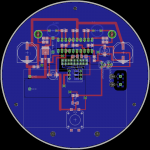
Regarding the layout, I followed every instruction in the TI notice. The only quirk I indulged myself was to use a VCC plane instead of a ground plane. But then again, I come from electronics not audio, so all these analogue stuff still looks like voodoo to me!
For reference I join an image of the layout (there is a HDCD radio receiver board that get soldered in the middle of the pcb, hence the 5v regulator and the button and status led).
I followed as closely as possible TI notice as they never failed me, but I didn't second guess what plus input and minus input meant, I just thought it was to say signal and ground.
I now see that indeed half of the chip is amplifying nothing! I would love to try both option "for science" (though as I don't have any testing equipment, my not-so-scientific ears would be the only judge).
For the version with output cap, [theAnonymous1] made it very clear how to do it. But how do you invert signal in BTL. Sorry if this is an obvious question but I really don't see. An opamp wired as an inverter?
Regarding the layout, I followed every instruction in the TI notice. The only quirk I indulged myself was to use a VCC plane instead of a ground plane. But then again, I come from electronics not audio, so all these analogue stuff still looks like voodoo to me!
For reference I join an image of the layout (there is a HDCD radio receiver board that get soldered in the middle of the pcb, hence the 5v regulator and the button and status led).
Attachments
Hi,
After testing, indeed, using it as a true stereo chip and using only one channel does indeed reduce noise. It is faint but audible. And to answer my own question, after a little research, to use it you have to transform tour single ended signal into a differential one.
Many ways to do it, but if I manage to put my hand on this , I'll try it out!
It's really not worth trying to run it bridged. The chip can't handle much current output, so with an 8 ohm load you will only gain 5W bridged.
For the cost and complexity of adding additional circuitry to run bridged, there are many more suitable class-d options out there.
I know you already put effort and money into your board, but I suggest either just using one channel or find another IC and start over.
For the cost and complexity of adding additional circuitry to run bridged, there are many more suitable class-d options out there.
I know you already put effort and money into your board, but I suggest either just using one channel or find another IC and start over.
Yeah, it kind of was my take on this too! Anyway the power output on one channel is more than sufficient for my needs.
The next version of my card will include the capacitor and everything will work out fine!
Honestly I was kind of blown away about how easy it is to work with those chips. I thought I was kind of reckless to send the pcb to the fab house without any breadboard pre-testing but in the end it turned out better than expected!
Thanks again for the advices!
I've had a couple pre-built amps based on TPA3123, which I understand is a related chip - one using the SE output with coupling caps, and one with dual chips in BTL, and I also noticed this type of distortion, particularly during sustained piano notes that don't provide much in the way of HF overtones to 'hide' this noise. It sounds like a noise gate opening up around the note. It led me to discard both these amps; one is on my desk at work and the other is not being used. I've decided this is most likely a problem in the design of the TPA3123 chip that was allowed to slip through for less-critical listening applications. The TPA3118 amp I use now (SMSL SA-36A Pro) is free from this noise and is a more refined sounding amp overall, probably a high water mark in the sound of IC-based Class D systems. It's the first IC-based Class D amp I've had that can compare on a similar level with my LM3886 amp.
If you are looking for a chip to run in dual-mono, check out the TPA3112, which is a single channel 25W chip.
If you are looking for a chip to run in dual-mono, check out the TPA3112, which is a single channel 25W chip.
- Status
- Not open for further replies.
- Home
- Amplifiers
- Class D
- Distorsion on High Frequency in TPA3122D2N