All:
Amazing! I watched several YouTube videos demonstrating how to use hot air and solder paste and really focused on using as little paste as possible, and still used too much. Given my slowly declining eyesight, I view SMD work with a lot of trepidation and yet recognize, given the industry's march in that direction, that it's something I'll need to master if I want to keep building audio projects.
As far as the board soldered with an iron is concerned, I have no excuse. Best intentions aside and recognizing there was little room for error I should have been more careful.
John:
Thank you!
Regards,
Scott
Folks:
All is well. A big kudos to JHH for stepping in and helping me. Certainly not expected and very much appreciated.
Many thanks,
Scott
All is well. A big kudos to JHH for stepping in and helping me. Certainly not expected and very much appreciated.
Many thanks,
Scott
johnhenryharris -
Thank-you for posting this project. I'm going to get the parts heading this way. I've not had PCB boards made, where would you suggest having these made?
Thank-you for posting this project. I'm going to get the parts heading this way. I've not had PCB boards made, where would you suggest having these made?
I use the Seeed Studio site which does a lot of things for Arduino, etc. 10 PCBs for $5 USD up to 4"x4", but shipping runs around $30 for priority shipping, less for post services.
see: https://www.seeedstudio.com/fusion_pcb.html?v=0525
see: https://www.seeedstudio.com/fusion_pcb.html?v=0525
PabloHoney01:
Where in the world are you? If you're located in North America, I'd be happy to mail you a board (plus the Hall effect sensor pcb), gratis.
Regards,
Scott
Where in the world are you? If you're located in North America, I'd be happy to mail you a board (plus the Hall effect sensor pcb), gratis.
Regards,
Scott
johnheneryharris - thanks for the information and link!
SRMcGee - Awesome, appreciate the offer! I'm in Ohio and if you have some to spare I'll purchase. Since I'm new to diyAudio, I'm unable to directly contact you to work out the details. Looks as you are able to reach out to me.
SRMcGee - Awesome, appreciate the offer! I'm in Ohio and if you have some to spare I'll purchase. Since I'm new to diyAudio, I'm unable to directly contact you to work out the details. Looks as you are able to reach out to me.
I was going to suggest new people reach out to others who have built already, I built and used a couple of the last batch of PCBs and gave the rest to my Audio Business friend who so putting them in his custom turntables. Usually you get 5 or 10 boards from a board house and only have to use one or two of each and have left overs without a purpose for them.
Scott (SRMcGee) reached out and graciously is getting set of boards heading my way. Looking forward to tackling this project.
None of this would be in my wheelhouse if it wasn’t for you guys helping others. I’m so grateful.
None of this would be in my wheelhouse if it wasn’t for you guys helping others. I’m so grateful.
Hi Pablo,
Have you done anything with the Arduino microprocessors, used the IDE to program them?
Have you done anything with the Arduino microprocessors, used the IDE to program them?
Raspberry Pi is different but the same. 🙂 You should do ok. I started using Arduinos about 2 years ago, a bit of a learning curve but not bad. It was when I started changing the processor registers that it got a bit more complicated, fortunately the IDE helps a lot with that. Reading the data sheet can be a bit frustrating but app notes and other users experience and examples help a lot. Enjoy.
SMD is good for some things where space is an issue, but I only them use in control applications. For analog audio quality some much larger resistors sound better in, say, a volume control circuit. When using SMD parts I try to keep them at 1206 size, smaller is just too hard to place by hand. 🙂 Used my lighted magnifier for working SMD, only way with my older eyes.snip, I view SMD work with a lot of trepidation and yet recognize, given the industry's march in that direction, that it's something I'll need to master if I want to keep building audio projects.
Snip
Final parts arrived last night and was able to get it all up and running!
Made a small change to the program to illuminate the top segment (A) for the number 6. Changed line 21 to: B10111110, //6.
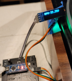
Have also experimented with an OLED display. Display uses IC2 comms which are on pins A4 and A5. Have to unsolder pins A4 and A5, so it's the LED's or OLED display. Wish the board has more AO's so I could run both simultaneously. This gives me an option for a small display to be placed near the TT.
Setting an a random box for now until I figure something else out. Gears are turnings in my head for a 3D printer to make an enclosure.
Here's some photo's. Thanks to John (johnhenryharris) for posting the project and to Scott (SRMcGee) for graciously sending me the boards!


Made a small change to the program to illuminate the top segment (A) for the number 6. Changed line 21 to: B10111110, //6.
Have also experimented with an OLED display. Display uses IC2 comms which are on pins A4 and A5. Have to unsolder pins A4 and A5, so it's the LED's or OLED display. Wish the board has more AO's so I could run both simultaneously. This gives me an option for a small display to be placed near the TT.
Setting an a random box for now until I figure something else out. Gears are turnings in my head for a 3D printer to make an enclosure.
Here's some photo's. Thanks to John (johnhenryharris) for posting the project and to Scott (SRMcGee) for graciously sending me the boards!
Nice. I tried the OLED display on prototypes, worked well but I couldn't find one in the size I wanted so went with the seven segment LEDs.
I've built a few of these for friends and managed to injure an led or 2 along the way so the OLED is a great low cost, lower effort way to get a working tach in some cases. Thanks again johnhenryharris for sharing this with the community. I'll post some pictures once I get a chance but for anyone who wants to build this with a 128x32 OLED (the 0.91" is what I used), here is the .ino. I'm sure there are 1000 ways to improve this but it's been many years since I had to write any code.
To get this working with the current pcb, don't install any of the display leds or resistors and connect the OLED to 5V, GND, A4 and A5 as usual. You still need the rest of the bits associated with timing (crystal, etc) but if you power directly through the arduino board, you can even omit the 7805 and caps.
Cheers!
Attachments

Nice job with the code, I had something like that in the prototype with the OLED.
Do you have a pic of your display?
Do you have a pic of your display?
- Home
- Source & Line
- Analogue Source
- Display Turntable speed with an Arduino Nano