No need to discuss "on how sensitive they are to regulation quality."
The TI data sheet gives PSRR: -140 dB typical, -120 dB maximum.
The TI data sheet gives PSRR: -140 dB typical, -120 dB maximum.

Should work fine but might be overkill for opamps.Its just for the supply on 2 OPA1612 gain stages - not the power stage. The 1ET400A DS lists a current requirement of 27mA for the second gain stage, and i'd have thought the buffer gain stage would use a similar amount, so unless i'm missing something we should be well under 100mA.
I'm just not sure whether there is likely much to gain by improving regulation on supply to OPA1612s. I cant find much discussion on how sensitive they are to regulation quality.
as far as i can see PSRR is between 70-80db over the audio range, but i think your point is still well made. It doesn't seem that additional de-noising is likely to improve anything audible.No need to discuss "on how sensitive they are to regulation quality."
The TI data sheet gives PSRR: -140 dB typical, -120 dB maximum.
The TI data sheet gives PSRR figures: 0.1 micro volt per volt ( 140 dB ) typical and 1 microvolt per volt ( 120 dB ).
Further down it gives curves. PSRR+ and PSRR- versus frequecy.
This shows flat 140dB from DC to 10 Hhz then decreasing 20dB per decade.
Hence 120dB at 100 Hz, mains hum in Europe.
This ripple is a sawtooth signal known to have harmonics amplitudes 1/k the fondamental amplitude, where k is the rank of the harmonic.
So, the significant ripple rejection is close to 120dB typical. OPA1612 is pretty good at PSSR.
Unfortunaltely there are other ways for the PSU ripple to sneak in.
A pitfall is the biasing circuitry. Make sure it is designed right.
Last edited:
This ripple is a sawtooth signal known to have harmonics amplitudes 1/k the fondamental amplitude, where k is the rank of the harmonic.
I am wrong about the 120dB. I overlooked, the rejected harmonics amplitudes do not decay.So, the significant ripple rejection is close to 120dB typical. OPA1612 is pretty good at PSSR.
The harmonics amplitudes do decay, but the rejection does so.
The result of these two effects is, all harmonics have the same amplitude.
All harmonics in the audio band. There are 200 harmonics up to 20 kHz
The RMS value of the rejected ripple is sqrt (200 ) less, that is 23 dB
So the 100Hz PSU ripple rjection is 97 dB.
Spend a little more money and a little more in-to-out voltage drop, upstream of the voltage regulator. Knock down the ripple by 60dB before the voltage regulator ever sees it.
In decibels, PSRR(output) = PSRR(upstream_stage(s)) + PSRR(voltage regulator).
In decibels, PSRR(output) = PSRR(upstream_stage(s)) + PSRR(voltage regulator).
Please educate me if I'm wrong here. The diodes hard switching off creates a lot of the harmonics we are trying to block with the PSRR of the upstream + regulator. Then another question, do the active based regulator boards also reduce the harmonics generated? Or am I totally off in left field?
The diodes switching, hard or not doesn't create lots of differential mode harmonics, which is what PSRR is about. The waveform is basically a sawtooth, containing even-order harmonics decaying relatively quickly with frequency.
"Dirty" diode switching generates mostly common-mode pollution between the transhormer and mains side and the rectified DC output, and to combat that you need a CM filter
"Dirty" diode switching generates mostly common-mode pollution between the transhormer and mains side and the rectified DC output, and to combat that you need a CM filter
My point was not about power supplies PSRR.Spend a little more money and a little more in-to-out voltage drop, upstream of the voltage regulator. Knock down the ripple by 60dB before the voltage regulator ever sees it.
In decibels, PSRR(output) = PSRR(upstream_stage(s)) + PSRR(voltage regulator).
My point was about OPA1612 PSRR, a related but different beast.
To hopefully show, there is no need for super duper PSU PSRR to deal with op amps based designs.
Hello Trileru thank you for sharing I accidentally found your post because I also happened to be looking for a supply regulator scheme for Wayne's BA2018 scheme. Because I have modified the scheme and layout, I will just change the name according to the version I made, because it is no longer original from Mr Wayne. I need a supply of around 15-25V. You can check the thread about my post here https://www.diyaudio.com/community/...waynes-ba-2018-linestage.423279/#post-7915193
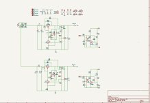
Don't think I posted higher Vout values so here's a 30Vout version. Didn't test more than 15Vout so can't say anything about tempco or regulation. I'll try to test 30Vout at some point, and post the results. If 15Vout is too low for you and you want 20-25V I'll post an update.
Attachments

If I use this schematic and create my own PCB layout design, I see AC voltage so I don't need to use a diode bridge, right? So I need to use an AC transformer to connect to the scheme?Don't think I posted higher Vout values so here's a 30Vout version. Didn't test more than 15Vout so can't say anything about tempco or regulation. I'll try to test 30Vout at some point, and post the results. If 15Vout is too low for you and you want 20-25V I'll post an update.
And if I use 22V AC voltage from a transformer will the scheme still work properly?
For 24Vout you can follow the 30Vout version I posted earlier and maybe drop R6/R18 to 6.8K and adjust Vout with R2/R14.
A 22VAC transformer should work for 24Vout. You need AC to DC bridge, maybe check the AC input PCB designs from post #209 and see how I did it.
If you design your own supply PCB I can't guarantee the performance from the measurements I made.
A 22VAC transformer should work for 24Vout. You need AC to DC bridge, maybe check the AC input PCB designs from post #209 and see how I did it.
If you design your own supply PCB I can't guarantee the performance from the measurements I made.
I recommend using the latest version of the circuit, example values in post #204. Just use a blue LED for D19/D23. All parts should be fine for 13Vout just adjust R18/R19.
Is it possible to design a fixed AC input and multiple voltage values +/- DC outputs?
Transformer is 58 - 0 - 58
Need +48 -48, +12.5, +17 - 17


Transformer is 58 - 0 - 58
Need +48 -48, +12.5, +17 - 17
Last edited:
Also needs to include this protection function on the new power supply PCB
FYI: PL is the front panel LED


FYI: PL is the front panel LED
- Home
- Amplifiers
- Power Supplies
- Discrete regulators with denoiser