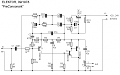
@ Salas:
Thank you for your advice!
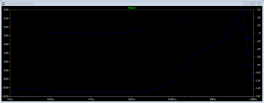
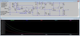
I have made the modification to the Riaa generator as you described, and it'a quite surprising to see the frequency response in the HF area. The green curve shows +20db around 1 Mhz and that is quite a lot. I wonder if adding a zobel network as suggested will make any difference (blue curve)?
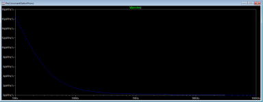
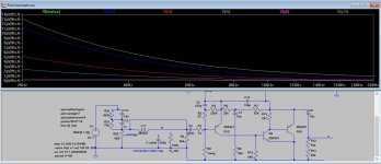
I also made a noise simulation with a different input capacitor, C1=500nF. It shows less noise, but only at the very low frequencies around 20Hz, and has almost no effect above 50Hz. The Riaa curve doesn't change much, only minor adjustments may be needed.
The strange noise described above seems to be a transistor related phenomenon called "popcorn noise", and the cure is finding and replacing the transistor.
@ Stocktrader200:
Changing the first transistor may be an option, I have 2N5209, 2SC945 and BC550 in my collection. Reducing R6 to 4k7 will double the gain and reduce the noise a little. It will also alter the riaa equalization, so some adjustment will be needed there too.
On the other hand, if we reduce R4~R6 and R24 with a factor 100, and increase C2 and C2 100 times, then the noise will be reduced around 4 times. Maybe that is the way to go?
Anyway, the preamp is now inside the main amp case, so any modifications will be made next time it is opened for service and modifications. In the meantime, maybe it would be fun to start on another Riaa preamp project.....?
You don't need the E2 dependent source either in this simulation. Relaxing the supersonic response should make a difference indeed. As for achieving less noise, since it integrates from the circuit's full bandwidth to an RMS value its good to control its quantity even in places below or above the audio band. Strange noises can also stem from some instability in a not yet finalized circuit.
You can try this one, which I use since its release until now. Sounds pretty good, neutral.... In the meantime, maybe it would be fun to start on another Riaa preamp project.....?
Attachments

Do you want to build this?
I like to use styroflex condensers for the RIAA-Network and find it difficult to realize these 8n2 and 12n capacitors.
So I changed some values to use better available parts. Not build yet, but the simulation is OK.
I like to use styroflex condensers for the RIAA-Network and find it difficult to realize these 8n2 and 12n capacitors.
So I changed some values to use better available parts. Not build yet, but the simulation is OK.
Attachments
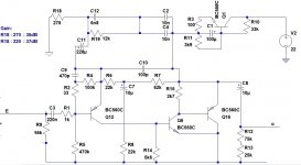
BC560C went recently obsolete but BC327-40 would be as good in this circuit, even less noisy (?)
You can get BC550/560 at reichelt.de, (probably from CDIL, because they offer this data sheet for download), for 5 cents per transistor.
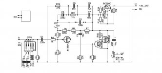
Most of the noise is produced by the first transistor Q12 and resistors R4-5. If you change the Rs, you can reduce a lot. At least in the simulation.
With my BC327-model the displayed noise increases.
Most of the noise is produced by the first transistor Q12 and resistors R4-5. If you change the Rs, you can reduce a lot. At least in the simulation.
With my BC327-model the displayed noise increases.
Attachments
I can't buy from reichelt.de, but I can buy 2n5551 and 2n5401 from tme.eu. Are these transistors a good replacement?
Why? 8n2 and 12n are well included in the E10 standard?I like to use styroflex condensers for the RIAA-Network and find it difficult to realize these 8n2 and 12n capacitors.
Surely not. They're more powerful, but also a bit more noisy, and consequently aren't dedicated for low noise applications.BC560C went recently obsolete but BC327-40 would be as good in this circuit, even less noisy (?)
Best regards!
And some questions...C1-220nF can be Orange Drops, all capacitors up to 12nF to be styroflex, all electrolytic capacitors to be Elna Silmic II,except C9 - Nichicon UPM? Can be increased the gain without damage of performance? MANY THANKS...
Alex Nitkins original design earlier in this thread has the advantage that the current noise is very low, so it will perform better than a bipolar input stage. The noise voltage may be a bit higher than a good bipolar, but that is more than compensated for by the low noise current. Most of the total noise in an MM input stage above about 3kHz is caused by current noise flowing through the real part of the loading resistor (47k) and the cartridge inductance plus the coil resistance. Use a good JFET like an LSK389 a d wire the two devices in the package in parallel
"... caused by current noise flowing through the real part of the loading resistor (47k) and the cartridge inductance plus the coil resistance."
Have a look at p.321 of the book you're holding up to the camera, in your selfie photo avatar at the top left of your post. It's entitled Cartridge load synthesis for lower noise.
2n5551 and 2n5401 will work.
But the simulation shows more noise.
Even BC557 and BC327 simulates better in this circuit.
The shown noise difference between BC560/557/327 is marginal in this circuit.
However, don't know how acurate the transistor-models are, I got them from there: Standard.bjt - LTwiki-Wiki for LTspice
Ok, eg. one could parallel 7x 1nf or 4x 1.5nf +1x 1.2nf, but that would require to much space on the PCB.(my thinking...)
I think that's largely a matter of taste.
I would suggest WIMA MKS2: 10µF, 220nF.
The two electrolytics, as you wrote. Others in Styroflex.
The gain can be increased to a certain extent by decreasing R12, 270 ohms (circuit in post #42). If you go too far down, the RIAA accuracy will decrease, then you will also have to change other values. (R6,7,11, C3,5,6,7)
270 Ohm -> 35 dB (RIAA: +-0.05 dB (20-20000 Hz))
220 Ohm -> 37 dB
150 Ohm -> 40 dB (RIAA: +-0.1 dB (20-20000 Hz))
But the simulation shows more noise.
Even BC557 and BC327 simulates better in this circuit.
The shown noise difference between BC560/557/327 is marginal in this circuit.
However, don't know how acurate the transistor-models are, I got them from there: Standard.bjt - LTwiki-Wiki for LTspice
Yes. But I can buy only 1, 1.2, 2.2, 3.3, 4.7, 6.8, 10 values in Styroflex at my preferred dealers.Why? 8n2 and 12n are well included in the E10 standard?
Ok, eg. one could parallel 7x 1nf or 4x 1.5nf +1x 1.2nf, but that would require to much space on the PCB.(my thinking...)
Yes. But I don't know "orange drops", if you mean Tantals, I say: NO NO NO ...C1-220nF can be Orange Drops, all capacitors up to 12nF to be styroflex, all electrolytic capacitors to be Elna Silmic II,except C9 - Nichicon UPM?
I think that's largely a matter of taste.
I would suggest WIMA MKS2: 10µF, 220nF.
The two electrolytics, as you wrote. Others in Styroflex.
The gain can be increased to a certain extent by decreasing R12, 270 ohms (circuit in post #42). If you go too far down, the RIAA accuracy will decrease, then you will also have to change other values. (R6,7,11, C3,5,6,7)
270 Ohm -> 35 dB (RIAA: +-0.05 dB (20-20000 Hz))
220 Ohm -> 37 dB
150 Ohm -> 40 dB (RIAA: +-0.1 dB (20-20000 Hz))
Attachments
Last edited:
....I don't know "orange drops", if you mean Tantals....
It's a USA thing:
Attachments
Have a look at p.321 of the book you're holding up to the camera, in your selfie photo avatar at the top left of your post. It's entitled Cartridge load synthesis for lower noise.
Indeed. I am aware of that technique - effectively ‘cartridge cooling’. I thing Marcel came up with that one and you can get IIR 3 dB lower noise which is not to be sniffed at.
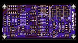
Some time ago I made a PCB layout for the "PreConsonant"(as in post #42 or #47)
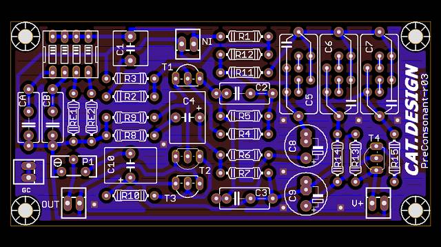
If anyone is interested in building this:
Gerber files see attached *.ZIP below
If anyone is interested in building this:
Gerber files see attached *.ZIP below
Attachments
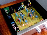
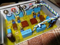
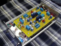
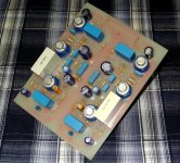
Hello ! This is an interesting topic . Now I also use several discrete phono stages . They are made according to the schemes of the 60s-70s . Some of them contain silicon transistors , the other part-germanium transistors . I like the sound of these old simple circuits .
Attachments

- Home
- Source & Line
- Analogue Source
- Discrete phono stage, single supply.