Hi guys, (not sure it's the right forum)
i'm looking into building myself a new phono preamp, i'm in a recording studio environement and i'm looking for transformer balanced outputs circuits.
I often build mic preamps using discrete opamps like the Api 2520 and John Hardy's 990c, they are still very often used in studios for their sound and drive abilities.
The schematic are out there for phono preamps but i find very little info on people who have used or build them.
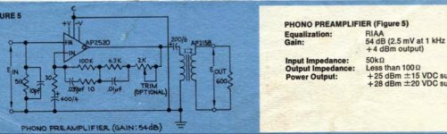
See attached pictures of a phono pre based around the Api 2520 and 990c opamps.
Has anybody has experience with them or what do you think of the topologies?
thanks,
John
i'm looking into building myself a new phono preamp, i'm in a recording studio environement and i'm looking for transformer balanced outputs circuits.
I often build mic preamps using discrete opamps like the Api 2520 and John Hardy's 990c, they are still very often used in studios for their sound and drive abilities.
The schematic are out there for phono preamps but i find very little info on people who have used or build them.
See attached pictures of a phono pre based around the Api 2520 and 990c opamps.
Has anybody has experience with them or what do you think of the topologies?
thanks,
John
Attachments
IIRC from the 990c app notes, the thinking is the same as it is in power amps: to isolate the opamp from capacitive loads (which could destabilize the opamp) without introducing significant Z at audio frequencies.... I'm not sure what the output RL brings to the table. Is this part of an emi filter?
Thanks guys! i wasn't aware it was a Lipschitz, i will read more on it.
here's the spec on the api https://www.steampoweredradio.com/pdf/api/manuals/api 1972 schematics.pdf
It says gain greater than 110db dc, gain bandwidth product 55mhz. not sure how it applies here.
very interesting tho, i might try it.
Do you guys see any disadvantage on using this topology? Or i should look at other designs with passive riaa network instead and adding a transformer balanced output?
That's a neat discrete opamp, would be absolutely worth trying. The trafo output is worth the effort if you are wanting to integrate it into your recording chain.
Alternatively, for balanced output, you can look into the excellent THAT 1646 or TI DRV134 series of balanced line drivers.
Alternatively, for balanced output, you can look into the excellent THAT 1646 or TI DRV134 series of balanced line drivers.
All that means is that it is one of several NFB networks identified by Stanley Lipschitz in his 1979 RIAA paper, but as he identified them all it doesn't really add much information.I wasn't aware it was a Lipschitz, i will read more on it.
API's plan is +/-0.5dB 20Hz to 6kHz, rising beyond.

More than good enough for me, but I have seen gold-ears work toward 0.25dB error.
More than good enough for me, but I have seen gold-ears work toward 0.25dB error.
I wonder what the trim pot is for.
Does anyone know the input noise current density of the op-amps?
Does anyone know the input noise current density of the op-amps?
If this schematic is correct, the API2520's input noise current will be just fine for an MM RIAA amplifier.
https://cdn.slidesharecdn.com/ss_th...55-lva1-app6892-thumbnail-4.jpg?cb=1439166459
The 990's input stage is biased at a higher than optimal current for MM, but not to such an extent that you are likely to notice it. It should be very suitable for MC.
http://www.johnhardyco.com/pdf/990.pdf
https://cdn.slidesharecdn.com/ss_th...55-lva1-app6892-thumbnail-4.jpg?cb=1439166459
The 990's input stage is biased at a higher than optimal current for MM, but not to such an extent that you are likely to notice it. It should be very suitable for MC.
http://www.johnhardyco.com/pdf/990.pdf
Last edited:
Not with the circuit you've drawn here. You have the opamp upside down.API's plan is +/-0.5dB 20Hz to 6kHz, rising beyond.
😱🤢👍You have the opamp upside down.
That's one reason I do not trust this sim further than I can throw it. Wired as drawn it should blow-up; yet I have run a dozen simulations on this sim-mule. FWIW, when I wire it "right" I get the exact same response. But don't trust me.
Have you tried a transient analysis? Is the op-amp just a controlled source with high gain?
I think it should blow up in a transient analysis, even if the op-amp is just an ideal controlled source. With an ideal controlled source and no reactive elements in the feedback (hence no poles to move into the right half plane), it might even work in a transient run.
I think it should blow up in a transient analysis, even if the op-amp is just an ideal controlled source. With an ideal controlled source and no reactive elements in the feedback (hence no poles to move into the right half plane), it might even work in a transient run.
Last edited:
I forgot to mention that you may need a transient stimulus for it to blow up in a transient analysis. Otherwise it may just stay in its bias point, even though it's an unstable bias point.
I guess to trim the RIAA response. It's inherently wrong, with an extra zero due to the 10R. Haven't read Lipschitz ...I wonder what the trim pot is for.
Thought this had some useful info- https://www.ti.com/lit/an/snaa046a/...35806&ref_url=https%3A%2F%2Fwww.google.com%2F
It's old and I don't use passive EQ, but still worth reading.
It's old and I don't use passive EQ, but still worth reading.
- Home
- Source & Line
- Analogue Source
- Discrete opamp RIAA preamps