I don't know what to do. I don't have equipment that can actually measure this kind of distortion. If I can't believe the simulation, then I might as well quit and stick with op amps and gain clones.
Believability isn't a yes or no thing, it comes in degrees. I think simulators are very useful and can give fairly accurate results if good models are used. But even if the sim can't tell you exactly what the distortion of your amp is, it can still tell you if this circuit has much lower distortion than that circuit.
The simulator can also be very useful when looking at other aspects besides distortion, e.g. PSRR, slew rate, stability etc.
And yes, Rome wasn't built in a day. This began iirc as a question of potential improvement on a stock line amp, and has turned into a wonderful educational experience, of far greater value I should think than shaving THD off of a suboptimal design. However, if one expects to become a world-class designer of small signal electronics overnight, it would take something like a super-Vulcan mind meld.
If it ceases to be fun, why bother? That's the problem I have sometimes when I consult: if I can't figure out something at least a little new to do, it's very boring. One idiot client revealed to one of his employees that he knew I had a big three-ring binder full of schematics, and that I'd wait a decent interval, open to one, extract it and scan, and then invoice him for many hours of work. Nope. Not the way I operate, and proprietary is proprietary, at least until it gets totally superceded.
Wow, you do this professionally? Thank you very much for your advice if that's the case! I feel privileged to learn from someone such as yourself.
I haven't given up, I'm just wondering how much I should believe Tina, how much I should change the parts as you suggest in spite of what Tina says, and so forth. Tina does provide all of the mathematical models it uses for each device, including definitions for all of those parameters in each spice model. I don't pretend to understand it at all.
Well, I already bought 40 of the A1015 PNP transistors, and 10 matched pairs of D667 and B647 transistors. I might as well use those even though I don't have a spice model for them. I think the A1015 is in the same ballpark as the BC560, and the other two are kind of like the BC327 and BC337. Anyway, I use the other features of the circuit with these transistors and probably get a good result.
Oops, I am mistaken. the A1015 only has a hfe of 80-400 whereas the BC560C is really high at 848. I replaced the BC560C in the circuit with something that has a lot less gain. Oh well, this is what I have to work with now.
Oops, I am mistaken. the A1015 only has a hfe of 80-400 whereas the BC560C is really high at 848. I replaced the BC560C in the circuit with something that has a lot less gain. Oh well, this is what I have to work with now.
Last edited:
Well, I already bought 40 of the A1015 PNP transistors, and 10 matched pairs of D667 and B647 transistors. I might as well use those even though I don't have a spice model for them. I think the A1015 is in the same ballpark as the BC560, and the other two are kind of like the BC327 and BC337. Anyway, I use the other features of the circuit with these transistors and probably get a good result.
The 1015 and its complement the 1815 are my favorite general-purpose transistors, something that proved I could learn something from my Chinese brothers (they were recommended by Dai Hwa as good for all sorts of things). The surface mount equivalents are the 2SA1162 and 2SC2712. The Toshiba ones are preferred. Get the highest beta code ones if possible, the BL suffix for the 1815 and the GR suffix for the 1015.
I used about 80 of these in SM for the signal processing in the JBL On Tour*, mostly for discrete opamp-like circuits. I started off with low-power ~audio quality IC opamps, but Gina Harman declared that the cost of the SKU had to be cut in half. And yes, DSP was out of the question at that time due in part to too-high power consumption (this runs off of 4 AAA cells, although it has as well an adapter supplied). By the way, before someone complains of the on-axis HF excess, I had to comply with the wishes of the then-speaker guy that made his determinations, and loved to see lots of high frequency response. That also made achieving decent signal-to-noise essentially impossible 😡
And yes, I do this for a living, although I've been wondering what's become of my clients recently 🙁. So I'm working on some speculative things at the moment.
But back to the transistors: be mindful of the breakdown voltages. The 1015 is fine for the input diff pair provided the input isn't drastically overdriven. For the second stage I believe someone mentioned the 2SC1845, which is also a fine part. So far the KSC devices seem to work well too, and Toshiba and others find less and less interest in staying in the discretes biz.
Brad Wood
* the manufacturer of the "filterless" class D output amps in On Tour, Microsemi, told me that a Chinese company tried to reverse-engineer the product. They gave up, with the guy assigned to trace out the circuit (it's also a four-layer board) probably threatening to jump out a window 😱 But perhaps surprisingly, the discrete Qs in volume and all the Rs and Cs came in cheaper than opamp solutions would have. If you own one take at least one of the batteries out if you are not going to use it for a while, as one of the ugly compromises was based on the unavailability of a switch that would competely disconnect them when the case is closed, and there is a small drain. Sorry about that.
I have 40 of the A1015Y, middle of the pack hfe.
Thanks again for your help and suggestions.
I found that I could switch the model the Tina uses to a SPICE-BJT one that has a bunch more parameters specified. It didn't make a huge difference.
With normal BJT devices, bandwidth is about the same with a nice smooth roll off above 1MHz. I'm fiddling with the current in the VAS right now. It seems that if I reduce it, the distortion goes down, though I'm not sure why or if I believe it. I've varied between about 3.5mA and 10mA.
Found another mistake on my part. I looked at the specs for the D667 and B647 and realized that the BC337 and BC327 have much higher hfe. So I found some other transistors that are more similar in that respect to the D667 and B647 with hfe between 100 and 200.
Last edited:
The aging BC639/640 are similar, but lower spec than the 2SD667/2SB647 pair - the latter are somewhat unique in specs. BC327/337 are a nice pair, except for their low Vceo. 2n5401/5551 have very good Vceo, Icmax, moderate beta and are available by the ton in both TO92 and SOT23, thanks to our Chinese friends who have cloned them. I'd recommend them for any new designs at all moderate-current locations.
For low-noise, low Ic, moderate Vceo NPN TO92 applications, there is probably nothing quite as linear as NEC 2sc1845, recommended earlier. It's way better than the bc550c, and generally higher beta. I'm anticipating end-of-life on these beauties - they're showing up in surplus lots and I stocked up several thousand for the rainy day. The complement, 2sa992 is also very nice, but much harder to find in surplus lots. The Toshiba 2sa970/c2240 pair is very similar.
The Toshiba 2sa1015/c1815 are widely available and inexpensive, but have much lower VCeo as well as beta, balanced by higher usable Ic. No usable LTSpice models, though - everything is wildly optimistic.
The aging BC639/640 are similar, but lower spec than the 2SD667/2SB647 pair - the latter are somewhat unique in specs. BC327/337 are a nice pair, except for their low Vceo. 2n5401/5551 have very good Vceo, Icmax, moderate beta and are available by the ton in both TO92 and SOT23, thanks to our Chinese friends who have cloned them. I'd recommend them for any new designs at all moderate-current locations.
For low-noise, low Ic, moderate Vceo NPN TO92 applications, there is probably nothing quite as linear as NEC 2sc1845, recommended earlier. It's way better than the bc550c, and generally higher beta. I'm anticipating end-of-life on these beauties - they're showing up in surplus lots and I stocked up several thousand for the rainy day. The complement, 2sa992 is also very nice, but much harder to find in surplus lots. The Toshiba 2sa970/c2240 pair is very similar.
The Toshiba 2sa1015/c1815 are widely available and inexpensive, but have much lower VCeo as well as beta, balanced by higher usable Ic. No usable LTSpice models, though - everything is wildly optimistic.
So many times the parameters of interest turn out to have emerged from a manufacturer's attempt to optimze something else. A good example is the Motorola version of the 2N4403, which was discovered here and there (and even kept as a trade secret sometimes) to have very low rbb'.
Agree about some of the models of the 1015 and 1815 being inaccurate, although I've wound up customizing mine because for one thing the beta was actually pessimistically low (presuming one can source the high-beta color codes).
The 5401/5551 parts are another example of fortuitous characteristics emerging, in that case high breakdown voltages for some chip designs coming along with very constant beta versus collector current (often referred to as "linear" beta, which is a prevalent misnomer, unless one insists that y = zero*x + constant is a linear function). However as I mentioned somewhere else, if the device dissipation varies the beta changes just like in other bipolars, and if this variation is unfolding at a low signal frequency, low enough that the chip thermal time constants are relatively fast enough, you can still get significant signal-frequency beta variation.
A lot of parts are entering end-of-life in through-hole, which is inconvenient, and some never even existed thus (the NXP BF862 for example). When Toshiba discontinued the dual JFETs in the funny packages, they "helpfully" made available a couple of pairs in SM. One problem: They have only five leads, with the sources tied together in the package. Thanks a bunch! 😡
Does anyone know how to turn this into a spice model device I can use in Tina?
.MODEL 2SA1015 PNP
IS=10.0004F
BF=239.283
NF=996.198M
VAF=100
IKF=172.882M
ISE=43.1361F
NE=1.44709
BR=5
IKR=961.305
ISC=121.849F
RE=1.05432
CJE=2P
MJE=500M
CJC=15.6333P
VJC=700.001M
MJC=499.871M
TF=601.795P
XTF=163.532M
VTF=9.93432
ITF=9.63234M
TR=10N
Thanks in advance.
.MODEL 2SA1015 PNP
IS=10.0004F
BF=239.283
NF=996.198M
VAF=100
IKF=172.882M
ISE=43.1361F
NE=1.44709
BR=5
IKR=961.305
ISC=121.849F
RE=1.05432
CJE=2P
MJE=500M
CJC=15.6333P
VJC=700.001M
MJC=499.871M
TF=601.795P
XTF=163.532M
VTF=9.93432
ITF=9.63234M
TR=10N
Thanks in advance.
Tina takes the standard spice files as far as I know. Not sure what else she takes... hmmm....🙄
Here is how to do it:
Put the spice model in a text file, e.g. with Notepad.
Store the file as e.g. 2SA1015.lib
Open Tina and go to Tools -> New Macro Wizard.
Choose a macro name, e.g. 2SA1015.
Click on the folder icon and locate the 2SA1015.lib file.
Click Next >.
Click Next > again.
Store it as 2SA1015.TSM in the Macrolib.
The macro is now ready to use and you can insert it immediately. Or you can insert it later via Insert -> Macro...
Once you start the macro wizard it is actually straight forward. You don't even have to tell Tina what symbol to use. I just tried it with your model and made a small test circuit to verify that it works as intended. At least it works as a PNP transistor🙂
Here is how to do it:
Put the spice model in a text file, e.g. with Notepad.
Store the file as e.g. 2SA1015.lib
Open Tina and go to Tools -> New Macro Wizard.
Choose a macro name, e.g. 2SA1015.
Click on the folder icon and locate the 2SA1015.lib file.
Click Next >.
Click Next > again.
Store it as 2SA1015.TSM in the Macrolib.
The macro is now ready to use and you can insert it immediately. Or you can insert it later via Insert -> Macro...
Once you start the macro wizard it is actually straight forward. You don't even have to tell Tina what symbol to use. I just tried it with your model and made a small test circuit to verify that it works as intended. At least it works as a PNP transistor🙂
Oh man! thank you so much! I'll give it a shot.
Hey, it worked! Thank you so much!
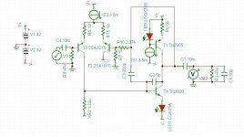
Without the buffer, performance is still good but it is sensitive to load impedance. I've juiced up the VAS and it's more happy that way. I was able to cut way back on the Miller capacitor. Bandwidth is good, with a nice smooth roll off at about 2MHz. Distortion is generally 0.0002->0.00038% depending on the frequency and load. I call this version 1.2, no buffer.
Without the buffer, performance is still good but it is sensitive to load impedance. I've juiced up the VAS and it's more happy that way. I was able to cut way back on the Miller capacitor. Bandwidth is good, with a nice smooth roll off at about 2MHz. Distortion is generally 0.0002->0.00038% depending on the frequency and load. I call this version 1.2, no buffer.
Attachments
Hey, it worked! Thank you so much!
Without the buffer, performance is still good but it is sensitive to load impedance. I've juiced up the VAS and it's more happy that way. I was able to cut way back on the Miller capacitor. Bandwidth is good, with a nice smooth roll off at about 2MHz. Distortion is generally 0.0002->0.00038% depending on the frequency and load. I call this version 1.2, no buffer.
Your Miller cap is now the 220 + 5 pF. The schematic might make it appear as if it is the 5 pF, but note that with the loss of the buffer (which accounts for the sensitivity to loading) the two caps are now in parallel.
Check out my fully-discrete opamp design, the LF03:
http://www.diyaudio.com/forums/analog-line-level/207871-lf03-discrete-opamp.html#post2928775
Highlights: Excellent sonics, which are nearly independent of load from 600 ohms to 10k and beyond, 10 MHz GBW with typical TO92 commodity transistors, quiescent current in the 5-10 mA range, +/- 10V output swings at +/- 15V rails (not great, but fine for line-level applications), retrofit replacement for existing DIP8 bipolar-input dual-opamps.
Your Miller cap is now the 220 + 5 pF. The schematic might make it appear as if it is the 5 pF, but note that with the loss of the buffer (which accounts for the sensitivity to loading) the two caps are now in parallel.
Yes. that's true.
It looks like a buffer is a good idea regardless of how much I try to make this thing perform well.
Miller cap is now 47pF. Response rolls off nicely beyond 10MHz. It's still load sensitive. I wonder if Tina can figure out the output impedance for this circuit?
Last edited:
Check out my fully-discrete opamp design, the LF03:
http://www.diyaudio.com/forums/analog-line-level/207871-lf03-discrete-opamp.html#post2928775
Highlights: Excellent sonics, which are nearly independent of load from 600 ohms to 10k and beyond, 10 MHz GBW with typical TO92 commodity transistors, quiescent current in the 5-10 mA range, +/- 10V output swings at +/- 15V rails (not great, but fine for line-level applications), retrofit replacement for existing DIP8 bipolar-input dual-opamps.
Oh, if I was designing this from scratch, it wouldn't look like this at all. I'm trying to optimize an existing circuit board that I have already purchased.
For example, I tried a current mirror as the active load for the LTP, and it made a huge difference in lowering distortion. But, adding something like that to these circuit boards is really hard, so I'm not planning on doing that. Trying to make something useful with these boards has been a real challenge. I might as well use another board I have that already has a buffer on it.
Last edited:
Yes it's easy and IMHO a very good test to do!I wonder if Tina can figure out the output impedance for this circuit?
Just short the input of the amp, apply the AC signal from the signal generator to the output of the amp through a 1Megohm resistor, and measure the AC voltage at the output of the amp.
The 1M resistor and the output impedance form a voltage divider, so it's easy to work out. E.g. If you apply 1V through a 1M resistor, and measure 1mV at the output, it means the output impedance is 1K. If you measure 0.2mV, it means the output impedance is 200R.
Why I like this is it gives an easy way to check stability into capacitive loads. With many/most amps, the output impedance rises at high frequencies. If the phase exceeds 90 degrees at any frequency, that means the amp will be unstable with some or other value of capacitive load. One AC sweep tells you all you need to know - easier than trial and error with various different capacitive loads.
You may also want to try with the input open circuit instead of shorted to earth as that may affect the result.
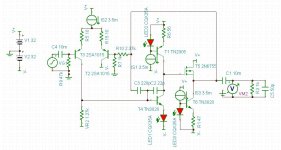
If I add a simple single ended MOSFET follower with constant current load, performance goes up dramatically. Here it's driving a 1k ohm load with 0.0003% distortion. I guess I can treat this thing more like a tube preamp with all single ended circuitry. One thing I learned is that adding a follower like this really increases the bandwidth and almost always introduces a RF resonance, so the feedback compensation has to be adjusted when I do that.
Attachments
Last edited:
Yes it's easy and IMHO a very good test to do!
Just short the input of the amp, apply the AC signal from the signal generator to the output of the amp through a 1Megohm resistor, and measure the AC voltage at the output of the amp.
The 1M resistor and the output impedance form a voltage divider, so it's easy to work out. E.g. If you apply 1V through a 1M resistor, and measure 1mV at the output, it means the output impedance is 1K. If you measure 0.2mV, it means the output impedance is 200R.
Why I like this is it gives an easy way to check stability into capacitive loads. With many/most amps, the output impedance rises at high frequencies. If the phase exceeds 90 degrees at any frequency, that means the amp will be unstable with some or other value of capacitive load. One AC sweep tells you all you need to know - easier than trial and error with various different capacitive loads.
You may also want to try with the input open circuit instead of shorted to earth as that may affect the result.
Thanks! I'll give it a try later.
- Status
- Not open for further replies.
- Home
- Source & Line
- Analog Line Level
- discrete op amp