No, you can't skip the comparator if you want a clock output that is suitable as a master clock for a CD player (the purpose of the project). You could replace its functionality with discrete components, but it's not something I'd recommend.
Hi Anton
I've finished one LJC module today.
Measuring 4.93V on pin1 of AD8561 vs 5V.
Is it Ok ?
What kind of wire do you use ?
Thanks
I've finished one LJC module today.
Measuring 4.93V on pin1 of AD8561 vs 5V.
Is it Ok ?
What kind of wire do you use ?
Thanks
No, you can't skip the comparator if you want a clock output that is suitable as a master clock for a CD player (the purpose of the project). You could replace its functionality with discrete components, but it's not something I'd recommend.
Can you please elaborate?
What's the function of the comparator? Purely buffering?
thanks
@korben69: That's fine, well within margin. The output connector pattern suits SMA / SMB / SMC connectors, so usually you'd use something like RG316. The cabling isn't critical over very short distances, and the clock should be positioned very close to the point where it is to be used so that the transmission distance is kept very short. The clock isn't designed to drive a transmission line. Sorry about the late reply, I hope the answer is still useful.
@roender: No, I've already answered this question.
@studiostevus: The comparator is absolutely essential, it can't be omitted. Its function is to transform the two out of phase sinusoidal signals from the oscillator into a single squarewave. It's not merely a buffer.
@roender: No, I've already answered this question.
@studiostevus: The comparator is absolutely essential, it can't be omitted. Its function is to transform the two out of phase sinusoidal signals from the oscillator into a single squarewave. It's not merely a buffer.
Thanks for explaining.
Any idea about the effect of the comparator on jitter/phase noise...? The data sheet mentions a 7ns propagation delay, no mention of jitter (15ps typical i read somewhere). In any case, i believe that any psu noise to the comparator will result in phase noise...
Worth mentioning is also that not all devices require a square waveform to trigger. Have you tried to use it without?
The comparator will add some phase noise, but it's not separable from the rest of the design. However, what it adds is by far outweighed by what it does by providing a squared output and the cancellation of common mode noise from the oscillator.
Did you note that the comparator runs off a separate regulated supply to the oscillator?
As long as the waveform is of adequate voltage, almost any wave shape (triangle, sine etc) will work with almost any device. However, one of the significant causes of jitter is noise in the transition voltage of the receiving device. The jitter caused by this is proportional to the slope of the waveform about the transition, the steeper the slope the less jitter. Why would you want to use anything but a square wave?
In any case, i believe that any psu noise to the comparator will result in phase noise...
Did you note that the comparator runs off a separate regulated supply to the oscillator?
Worth mentioning is also that not all devices require a square waveform to trigger. Have you tried to use it without?
As long as the waveform is of adequate voltage, almost any wave shape (triangle, sine etc) will work with almost any device. However, one of the significant causes of jitter is noise in the transition voltage of the receiving device. The jitter caused by this is proportional to the slope of the waveform about the transition, the steeper the slope the less jitter. Why would you want to use anything but a square wave?
Thank you for your answer Anton.
Is there a big impact if I test the module without SMA/B/C connectors ?
I mean wire directly soldered to the board, distance wil be less than 15cm (-/+6 inches)
Is there a big impact if I test the module without SMA/B/C connectors ?
I mean wire directly soldered to the board, distance wil be less than 15cm (-/+6 inches)
No, it shouldn't be too bad. 15cm is actually substantial, try to keep it less than 10cm (ideally less than 5cm) if you can.
Patent 7,511,590
US patent 7,511,590 Date of Patent: March 31, 2009
Inventor: Mark Richard Gehring
Assignee: Cypress Semiconductor Corporation
😀
US patent 7,511,590 Date of Patent: March 31, 2009
Inventor: Mark Richard Gehring
Assignee: Cypress Semiconductor Corporation
😀
Not quite the same, is it...
By the way, the description of the circuit, and the purpose of the differential amplifier (common mode noise rejection) makes me think about the current circuit. Doesn't the use of the comparator completely defeat the purpose of the differential amp?? I mean noise seeps in again through the IC.......
By the way, the description of the circuit, and the purpose of the differential amplifier (common mode noise rejection) makes me think about the current circuit. Doesn't the use of the comparator completely defeat the purpose of the differential amp?? I mean noise seeps in again through the IC.......
Last edited:
Not quite the same, is it...
By the way, the description of the circuit, and the purpose of the differential amplifier (common mode noise rejection) makes me think about the current circuit. Doesn't the use of the comparator completely defeat the purpose of the differential amp?? I mean noise seeps in again through the IC.......
Check the datsheet. CMRR is typical 85dB for the AD8561...
CD-rom
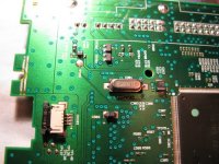
Anyone tried this in a CD-Rom?
i have a Plextor PX-712A used as transport and i really like it
have used different PS for it and have long time ago scrapped the SMPS and use aether batteries or a LM317 PS. (one for each voltage)
Under is a pic of the crystal, wold be fun to tweak this further
Any thoughts ?
Attachments
Hi All,
There's still been quite a bit of interest in this clock, so I've decided to do a second round. It'll be the same as the first round, except for a couple of changes:
- The kit prices will be USD30 for the DC powered version and USD40 for the AC powered version (including PCB). I lost money on the kits I sold in the first round, hence the change. The PCBs are still USD3.00 each.
- The components in the kit will be slightly different, but I might use different brands for the resistors and regulators. I'll post an exact bill of materials soon.
For more details, check back to the first post. I'll finish taking orders for the kits at the end of October (in a month), there won't be any particular deadline for the PCBs, I'll just sell them until I run out like last time.
Thanks,
Anton
Hi there,
In this second round GB, I would like to order:
2 x Kit for 7 - 20VDC powered version
2 x Bare PCB
Thanks
In this second round GB, I would like to order:
2 x Kit for 7 - 20VDC powered version
2 x Bare PCB
Thanks
- Status
- Not open for further replies.
- Home
- Group Buys
- Discrete Low Jitter Clock GB