Hi,
Could it works in order to obtain pro-audio frequencies ? (44.100khz, 48khz or 96khz)
Thanks
Could it works in order to obtain pro-audio frequencies ? (44.100khz, 48khz or 96khz)
Thanks
Hi Anton, I've build your clock, tested voltage on pin 1 of IC, but still figuring out how to connect the signal to the CD-72. I've tried signal on Xin and ground via R on Xout, or on full ground, but in both cases motor keeps spinning ....... , I guess because signal is not properly received. Any tips how I should connect properly?
Hi Anton, I've build your clock, tested voltage on pin 1 of IC, but still figuring out how to connect the signal to the CD-72. I've tried signal on Xin and ground via R on Xout, or on full ground, but in both cases motor keeps spinning ....... , I guess because signal is not properly received. Any tips how I should connect properly?
Hi:
I have the same problem as you!
The clock does not work in any of my CD players, based on TDA1541A.
I contacted the author of the project and he kindly told me to send them back him, to see if I burned some component in welding work.
Try to contact the author via private message. He is a very gentle person and willing to help.
had no issues with 11.2896 LJC clocks here, installed and running in both a marantz cd-95 and a micro cd-m2 with no problem
Hi Guys,
This is quite a robust design, and as long as it's been assembled reasonably well it should work. The first thing you should do when troubleshooting is to check the clock's output with an oscilloscope. Without one you're really flying blind. Without a 'scope, it'll be difficult to tell whether there's a problem with the clock itself, or a problem with the way it is installed.
Some of you don't have a 'scope, and while I think it is something that is a necessity for this type of work, I can help you out. You can send completed clocks back for me to test, and possibly fix. At least this way you'll know wgat the issue is.
Anton
Bare PCB
Hello Anton,
Do you have any PCB's left?
I've just found this theat, and I'd like to give it a try...
Jeroen.
Hello Anton,
Do you have any PCB's left?
I've just found this theat, and I'd like to give it a try...
Jeroen.
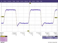
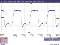
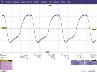
hi, I have a doubt, I played the circuit in simulation, and get this type of signal in scope, with the ad8561>

I thought it was bug in the model, and tested with lt1016 and the same result.
then the one who works is the AD8564,
what you think about it.
I thought it was bug in the model, and tested with lt1016 and the same result.
then the one who works is the AD8564,
what you think about it.
don't trust simulations of oscillators, unless you did them a lot of times and know how to do them.
Let it oscillate for a while, check the output after t=1s, 5s etc, see whether it gets more symmetrical.
Let it oscillate for a while, check the output after t=1s, 5s etc, see whether it gets more symmetrical.
If it happens, I would like a kit. In the mean time I have a question. What are the voltages for VCC, VCC1 and VCC2?
Anton, I would like to buy one Bare LJC clock PCB and one Unassembled LJC clock kitset. Thanks.
Hi Guys,
This is quite a robust design, and as long as it's been assembled reasonably well it should work. The first thing you should do when troubleshooting is to check the clock's output with an oscilloscope. Without one you're really flying blind. Without a 'scope, it'll be difficult to tell whether there's a problem with the clock itself, or a problem with the way it is installed.
Some of you don't have a 'scope, and while I think it is something that is a necessity for this type of work, I can help you out. You can send completed clocks back for me to test, and possibly fix. At least this way you'll know wgat the issue is.
Anton
Hi Anton,
I just got a low end USB scope and finished assembling the module, how to test if I am getting the clock runing?
Thanks
Hi.
Nicely done!
On that note: looking at the measurement graphs of the clock output (post #3), I am afraid there is an evil at work here.
Something's not right.... send me an email.
Keep up the good work!
Best regards;
Alexiss
Nicely done!
On that note: looking at the measurement graphs of the clock output (post #3), I am afraid there is an evil at work here.
Something's not right.... send me an email.
Keep up the good work!
Best regards;
Alexiss
Attachments
Last edited:
- Status
- Not open for further replies.
- Home
- Group Buys
- Discrete Low Jitter Clock GB