Ah, I get it. That capacitor can be rather good with an undersized box! Thanks. 🙂
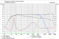
I set up an adequate 30L closed box 8" in the regular way. The dotted line. Then took it down to a mere 12L. That had a horrible 2dB bump at 100Hz.
Then apply the magic 450uF capacitor, and it looks a lot better which is the diagram. In fact, above 50Hz, it works better on flatness. One for the repertoire. Because I have some old undersized speakers that have defeated me for years.
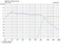
Second image is electrical response, if you want to see what it does. Nice. 😎
I set up an adequate 30L closed box 8" in the regular way. The dotted line. Then took it down to a mere 12L. That had a horrible 2dB bump at 100Hz.
Then apply the magic 450uF capacitor, and it looks a lot better which is the diagram. In fact, above 50Hz, it works better on flatness. One for the repertoire. Because I have some old undersized speakers that have defeated me for years.
Second image is electrical response, if you want to see what it does. Nice. 😎
Attachments
That's good. Perhaps my perception of changes in bass level with/without the cap, wasn't purely due to my over active imagination
To sum up the disadvantages that have been mentioned in this thread.
1. FE3T: "A tad higher group delay".
2. DDF: Non linearity in bass output with level. I wonder how noticeable this is.
3. System7: Reduction in damping factor. I have no means of measuring this, but my perception when switching from one speaker with the cap to the other speaker without, is that not only does the level of bass change but the quality does too. If I had the means, I would investigate further to see if I was simply imagining this.
Hello,
Are you aware that some amplifiers use a capacitor coupled output ??
So, there is a capacitor in serie with the loud-speaker !!
Are you aware that some amplifiers use a capacitor coupled output ??
So, there is a capacitor in serie with the loud-speaker !!
it works as a 1st order (6 dB) lowpassfilter at +/- 45Hz. It could help a small box to have more bass by removing signal before the driver that it can't produce. Like that the woofer does not have to spend much energy on them and can give a better bass above 45Hz. It's a trick often used in studio's also, remove rumble to improve the real sound. if it's a small box, it's normal that it's fs is above 45Hz so...
I would like to try out the effect of adding a series capacitor in one of my small closed box loudspeaker systems.
According to the second reference given in post #19, the correct value for the series capacitor involves calculation along with some empirical determination.
C = (K x Qts) / (Re x fs)
The constant K depends on the voice coil inductance.
For the 'standard type of woofer', a value of K = 265 is suggested.
A bit rough and ready perhaps, but a good starting point for experimentation!
it is more than just a 1st order filter. The response rises some before it drops off, unlike what would happen if you just put a 1st order filter ahead of the amplifier.
TBH, this is only about the third time this forum has surprised me, and I have actually learned something new. 😀
But this is a useful idea. And as geotone says, boxsim predicts it well enough. Seems like the capacitor interacts with the Fc in-cabinet resonance impedance peak in the undersize closed box to do something useful. Too big, and it does nothing, too small and it rolls things off to much. Presumably, as Fc goes lower, you need a bigger capacitor.
I was looking at alayn91's notion that single rail amplifiers might be deliberately exploiting this principle. It seems not. The output capacitors that I examined were much larger.
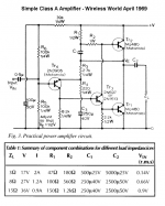
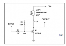
Below the 1969 John Linsley-Hood Class A amplifier. A design that is a bit of a classic. Polar electrolytics work very well when biased strongly, though people often recommend a parallel MKT bypass for the higher frequencies too. It inspired Nelson Pass and friends into some very surprising designs like the light-bulb amplifier, which doubtless needs a decoupling capacitor too.
The Class-A Amplifier Site
PassDiy
It's useful to know a bit about amplifiers, at least why they prefer flat and defined impedance, even if the feedback theory misleads you into thinking it shouldn't matter.
But this is a useful idea. And as geotone says, boxsim predicts it well enough. Seems like the capacitor interacts with the Fc in-cabinet resonance impedance peak in the undersize closed box to do something useful. Too big, and it does nothing, too small and it rolls things off to much. Presumably, as Fc goes lower, you need a bigger capacitor.
I was looking at alayn91's notion that single rail amplifiers might be deliberately exploiting this principle. It seems not. The output capacitors that I examined were much larger.
Below the 1969 John Linsley-Hood Class A amplifier. A design that is a bit of a classic. Polar electrolytics work very well when biased strongly, though people often recommend a parallel MKT bypass for the higher frequencies too. It inspired Nelson Pass and friends into some very surprising designs like the light-bulb amplifier, which doubtless needs a decoupling capacitor too.
The Class-A Amplifier Site
PassDiy
It's useful to know a bit about amplifiers, at least why they prefer flat and defined impedance, even if the feedback theory misleads you into thinking it shouldn't matter.
Attachments
Last edited:
I was looking at alayn91's notion that single rail amplifiers might be deliberately exploiting this principle. It seems not. The output capacitors that I examined were much larger.
Thanks for clearing that up.
The output capacitors in my vintage Rogers Ravensbrook amplifier are 1,500uF.
it is more than just a 1st order filter. The response rises some before it drops off, unlike what would happen if you just put a 1st order filter ahead of the amplifier.
It turns a closed box from 2nd order high pass to 3rd and vented from 4th order high pass to fifth with the cap just one reactive element in the filter. Target alignments are achieved by looking at the filter in its entirety
I was looking at alayn91's notion that single rail amplifiers might be deliberately exploiting this principle. It seems not. The output capacitors that I examined were much larger...
But it doesn't mean you can't adapt such amplifiers for it -- changing that output capacitor to (the right) smaller value could help bass response in such cases!
Another piece of information with another formula for selecting the series capacitor found on sbacoustics technical notes Technical Notes :: SB Acoustics
Wonder how this would work for dealing with a high Qts drivers in a closed box, which model with a hump around Fs, change in box size only seems to move the hump around. A series cap should lower the hump & extend low frequency response, but there's the complication of the impedance hump at resonance. There is a Neville Thiele paper about his, but the math is way beyond me. & his paper doesn't seem to take into account the resonant peak...???
The capacitor bank in my big sealed box subwoofer is ~1500uF and makes a big difference in perceived deep bass. 15" and fully stuffed 120 litre box.
It's actually a common technique in theory but not often used due to the cost of such large capacitance.
Possibly more often discussed in the subwoofer forum.
Quite often when scrapping cheap HTIaB speakers I find such capacitors in series with the tiny 70mm drivers
It's actually a common technique in theory but not often used due to the cost of such large capacitance.
Possibly more often discussed in the subwoofer forum.
Quite often when scrapping cheap HTIaB speakers I find such capacitors in series with the tiny 70mm drivers
I'll have to give it a try before I consign a bunch of Hi Q woofers to the garbage; have a couple of 10"ers which I think have Qt of ~.9; scored 4x 'white box' 8"woofers last week - Qts 1.9!!!
Be careful Pete as the cost of the capacitor banks can be worth a lot more than a cheap woofer. Unless you have a drawer full of 1000uF caps that is.
High "Q" woofers are for OB use, it's what I'm saving some of mine for.
High "Q" woofers are for OB use, it's what I'm saving some of mine for.
If that question was for me Allen then yes; about a decade ago in the subwoofer sub forum. With the generous assistance of several members much smarter than I am.
- Home
- Loudspeakers
- Multi-Way
- Disadvantages of Capacitor in series with main driver.