Plan is to add one more output pair, but that will require substantially bigger heatsink.
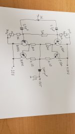
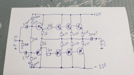
Right now it measures 0.011% thd at half a watt. With or without diodes, they are not needed.
Sounds great. Lot more testing comming.
Right now it measures 0.011% thd at half a watt. With or without diodes, they are not needed.
Sounds great. Lot more testing comming.
Attachments

Have been playing for few days, very happy with the sound.
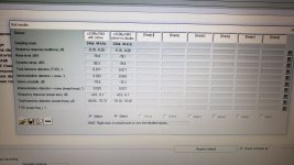
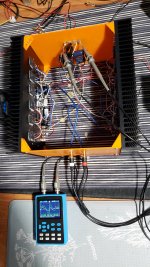
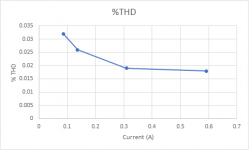
Started testing for distortion with regards to bias. Testing was done with speakers attached as load, moderate level, as i do not like it too loud. Lowest setting bias i started with was only 28mV on 0.25 ohm resistor. I had 0.25 instead of 0.22 in previous version. With 28mV it had about 0.050% distortion.
I started turning bias up, 48mV, 67mV and so on, with 100mV highest. With 100mV distortion dropped to 0.014%, which is respectable considering no feedback.
Attachments

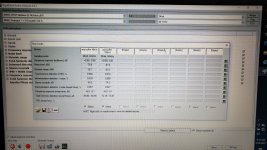
The relationship between the bias and distortion. Current per device. No surprise here.
No need to push bias too high, running at ~0.4A per transistor now.
Started testing buffer in the main system. Buffer has no sound of its own, just like F4, or very little. Sound is totally dominated by the pre.
No need to push bias too high, running at ~0.4A per transistor now.
Started testing buffer in the main system. Buffer has no sound of its own, just like F4, or very little. Sound is totally dominated by the pre.
Attachments

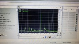
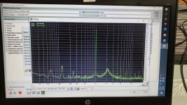
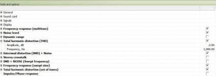
Here is distortion difference at two bias levels. And the harmonic profile.
Have not used RMAA for ages but from what i remember the free version was taking distortion measurements at a lower voltage level than what you see from the calibration test tone. Perhaps it was at -6db. I may be wrong but worth checking.
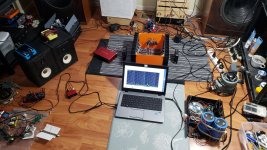
RMAA will allow you to proceed with measurement only if signal back on input is at least -10dB. It has red/green square to indicate this, that you reached enough input level. However, you can disable this function and proceed with measurements with the risk that it will not finish. It happened to me few times, it just reports 'could not lock on signal'. Or something like that. My soundcard (focusrite) has plenty of gain, I can measure at low or high level. I prefer to measure with actual speaker at normal listening level (less than 0.5 watt). That is relevant to me, distortion at actual listening level.
I do not care less what the distortion is at maximum power. Often the parameter touted most by many. How much time the signal spends at maximum power? Not to mention, at that loudness, who cares about distortion?
I do not care less what the distortion is at maximum power. Often the parameter touted most by many. How much time the signal spends at maximum power? Not to mention, at that loudness, who cares about distortion?
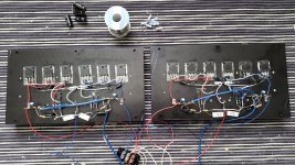
Some progress on the box.
Have not used RMAA for ages but from what i remember the free version was taking distortion measurements at a lower voltage level than what you see from the calibration test tone. Perhaps it was at -6db. I may be wrong but worth checking.
Thank you for this post. These videos have been driving me nuts. I built the circuits and they work, but LtSpice tells me it makes no sense. Now I know why 😂😂
- Home
- Amplifiers
- Solid State
- Direction of diodes in an amplifier