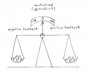
Yvesm said:Neutralization IS positive feed back intented to cancel negative feed back introduced by inter electrode capacitances, specially when exacerbated by Miller effect.
This seems to be another one of those ways to cheapen a design. After all, a couple of capacitors are a lot cheaper than a cathode follower. Something the pencil pushers would like. Rather than bother with something that finikey, I'd rather include cathode follower grid drivers that can source the current that charging the Ci requires to solve the slewing problem.
Yvesm said:Neutralization IS positive feed back intented to cancel negative feed back introduced by inter electrode capacitances, specially when exacerbated by Miller effect.
Yves.
hey-Hey!!!,
The C-miller is not NFB. It is a decreasing with frequency input impedance that rolls off the response at HF based on the ouput Z of the preceeding stage.
cheers,
Douglas
Bandersnatch said:
hey-Hey!!!,
The C-miller is not NFB. It is a decreasing with frequency input impedance that rolls off the response at HF based on the ouput Z of the preceeding stage.
cheers,
Douglas
C-Miller is the result of a NFB, it is a classical integrator on high frequencies.
Proposed neutralization is a PFB, with too big caps it may turn into a classical multivibrator.
Speaking of Miller capacitance think of a follower before a tube as the mean to shorten a time constant of that integrator. But the main reason is to reduce distortions caused by screen grid conductivity on positive voltages.
Though, any follower adds own distortions, so we are still optimizing things choosing less trouble from all combined troubles together.
In terms of distortions an emitter follower may be viewed as a solid state diode, a cathode follower -- as a vacuum diode, and a source follower -- as a charge controlled variable resistors. Even the latest one will introduce 2'nd order distortions, and move a time constant network on working frequencies from input of an output stage to input of a driver. First two are diodes in a signal path. The more open loop gain each of them have the shorted will be "a diode" part in respect to a signal level, but anyway it present.
So, "To use, or not to use -- that is the question" -- we have to choose for each particular design. No common recipe exist. But we have as always criteria of optimization.
neutralisation eliminates feedback
Hello Miles Prower,
Oh no, neutralisation looks easy but it is a very difficult thing to do.
Most technicians are not able to neutralize or to align the neutralisation.
Hello Wavebourn,
Do you know the TGTP / Huth-Kuehn oscillator?")
A neutralized stage has no feedback. #57
Kind regards,
Darius
Hello Miles Prower,
Originally #63 posted by Miles Prower
This seems to be another one of those ways to cheapen a design. ...
Oh no, neutralisation looks easy but it is a very difficult thing to do.
Most technicians are not able to neutralize or to align the neutralisation.
Hello Wavebourn,
Wavebourn said:
C-Miller is the result of a NFB, it is a classical integrator on high frequencies.
Proposed neutralization is a PFB, with too big caps it may turn into a classical multivibrator.
...
Do you know the TGTP / Huth-Kuehn oscillator?
A neutralized stage has no feedback. #57
Kind regards,
Darius
Attachments
When one of the output tubes cuts off there will be no Miller capacitance so in that case you will have nothing but positive feedback. You can of course argue that in a cut off situation there will be no amplification of the fed back signal.
Anyway, here is what can happen when an output stage moves from class A to B. This burst of hf might (or might not) turn on the tube in the passage from class A to class B and do "cross-over distortion".
You really don’t want to feed this signal back to anywhere in the signal path.
Jan E Veiset
Anyway, here is what can happen when an output stage moves from class A to B. This burst of hf might (or might not) turn on the tube in the passage from class A to class B and do "cross-over distortion".
An externally hosted image should be here but it was not working when we last tested it.
You really don’t want to feed this signal back to anywhere in the signal path.
Jan E Veiset
#68
Please read the technical forum rules below and use a source follower to drive the tube. Thanks.
 diyAudio technical forum rules:
µ = hfe_ hie = 1/hoe_ triodes don't change their characteristic at positiv grid voltages_ anode current is independent from g2 current in a pentode_ calculating the gain of a triode cathode follower you have to ignore the influence of µ_ ignore Loftin White_ ignore the fourth circuit topology_ tubes should be replaced by mosfets_ neutralisation is forbidden_ continued
Darius
Should I or should I  ...
...  -->
-->
Please read the technical forum rules below and use a source follower to drive the tube. Thanks.
diyAudio technical forum rules:µ = hfe_ hie = 1/hoe_ triodes don't change their characteristic at positiv grid voltages_ anode current is independent from g2 current in a pentode_ calculating the gain of a triode cathode follower you have to ignore the influence of µ_ ignore Loftin White_ ignore the fourth circuit topology_ tubes should be replaced by mosfets_ neutralisation is forbidden_ continued
Darius
Should I
or should I ... -->Er, Um, um.... what!
I think that a tube cutting off in P-P does not eliminate the Miller capacitance (cross coupling thru xfmr still making the plate swing), but it should drop about 15% without current thru the tube (space charge effect on internal C). (possibly causing oscillation around cutoff unless the neut. is trimmed a little below about 85% neutral, see JANE's graphic)
Similarly, for the neutralization effect in class AB. An ideal xfmr would still provide the inversion from the still driven side even if the cut off tube is not driving. A real xfmr would likely be causing some serious phase shift however at the high frequencies where neutralization is most active. But since it is positive feedback already by design, it should just be turning to negative feedback, making the miller cap. look worse. A problem would arise if the xfmr has a HF resonance that boosts the cross-coupled neutralization signal at some freq. So some HF RC snubbers on the primaries could be helpful if the triode plate Z and load Z are not sufficient to damp this out. Speaker reactance could also complicate matters.
Don
OT: UL possible here?
Hi, I am not using an output "Transformer" I am using an output "Uebertrager".
This makes a difference.
I am thinking about the so called UL (Ultra Linear) you know Blumlein
feedback to g2 from a tapping of the uebertrager.
This is impossible using a (mains-) transformer as an output uebertrager
because the frequency curve is non linear and sometimes the thing starts oscillating...
An excellent output uebertrager is essential in this topology.
Thus should we make a forum rule telling "UL is forbidden" in this forum?
Darius
Hi, I am not using an output "Transformer" I am using an output "Uebertrager".
This makes a difference.
I am thinking about the so called UL (Ultra Linear) you know Blumlein
feedback to g2 from a tapping of the uebertrager.
This is impossible using a (mains-) transformer as an output uebertrager
because the frequency curve is non linear and sometimes the thing starts oscillating...
An excellent output uebertrager is essential in this topology.
Thus should we make a forum rule telling "UL is forbidden"
in this forum? Darius
neutralisation eliminates feedback
Hello,
does this mean that
neutralisation is well accepted in the forum now?
Can I erase it from the list below?
Technical forum rules:
µ = hfe_
hie = 1/hoe_
triodes don't change their characteristic at positiv grid voltages_
anode current is independent from g2 current in a pentode_
calculating the gain of a triode cathode follower you have to ignore the influence of µ_
Loftin White is cathode feedback_
[D]ignore the fourth circuit topology[/D]_
tubes should be replaced by mosfets_
neutralisation is forbidden_
continued ...
Darius
Miles Prower said:
<snip>
No, of course not. Look around and you can probably find a torrent somewhere where you can gack Jones' book. There are lots of netizens with no regard for the IP rights of others. Can you live with your conscience though?
<snip>
Miles, thanks for making that comment. All too often there are those of us who forget that it takes work to create something of value, beyond the outright theft of someone else's work, the effort that went into creating that original value ought to be rewarded. How many of us would like to work for no compensation, while others profit by our efforts?
Now back on topic...
I suspect that the leakage inductance present between sections of the primary of a transformer would result in a less than 1:1 match when class B conditions exist in a class AB output stage, this might reduce the effectiveness of miller capacitance cancellation, however I have always also thought that trying to cancel (neutralize) all of the miller capacitance this way could be a risky proposition and tend to do less than 100% neutralization. (As pointed out it is positive feedback and applied to an extreme you have a multi-vibrator.) People may argue that this works well in RF amplifiers - however there is a fundamental difference in that small variable capacitors are usually used for this function - and the adjustment must be made every time you replace tubes in the final.
There is a WE 300B PP circuit using neutralization discussed on another thread, there they use 15pF per tube which I believe is significantly lower than the actual Cmiller, but I could be mistaken.
While I can see a good argument for CF in many applications there are some where the additional complexity, lack of space or a theoretical objection to the use of an additional stage might make C miller cancellation a somewhat attractive option.
Re: OT: UL possible here?
Hi Darius,
I don't think you would need "neutralization" with UL (red herring? ) as the output tube acts largely like a pentode from the point of view of the grid anyway and Cmiller should be much less than for triodes or triode connected pentodes. UL otherwise is just fine with anything other than mains transformers - I'm assuming the large leakage inductance could be getting you into trouble there. Am I missing something here?
In keeping with the subject of the original thread I would certainly advocate the use of direct coupled CF or George's power drive any time class AB2 operation is contemplated as part of the design criteria. I would also add transformer (IT) coupling to the list for SE or PP and will use it soon in a new amplifier design where I am looking for much more SE output power than is usually the case.. (GM70/845/211)
UL is approved in this forum, as are triodes, neutralization and anything else you might happen to like.. This is the place to express differing opinions - respectfully of course..
oldeurope said:Hi, I am not using an output "Transformer" I am using an output "Uebertrager".
This makes a difference.
I am thinking about the so called UL (Ultra Linear) you know Blumlein
feedback to g2 from a tapping of the uebertrager.
This is impossible using a (mains-) transformer as an output uebertrager
because the frequency curve is non linear and sometimes the thing starts oscillating...
An excellent output uebertrager is essential in this topology.
Thus should we make a forum rule telling "UL is forbidden"
Darius
Hi Darius,
I don't think you would need "neutralization" with UL (red herring?
) as the output tube acts largely like a pentode from the point of view of the grid anyway and Cmiller should be much less than for triodes or triode connected pentodes. UL otherwise is just fine with anything other than mains transformers - I'm assuming the large leakage inductance could be getting you into trouble there. Am I missing something here? In keeping with the subject of the original thread I would certainly advocate the use of direct coupled CF or George's power drive any time class AB2 operation is contemplated as part of the design criteria. I would also add transformer (IT) coupling to the list for SE or PP and will use it soon in a new amplifier design where I am looking for much more SE output power than is usually the case.. (GM70/845/211)
UL is approved in this forum, as are triodes, neutralization and anything else you might happen to like..
This is the place to express differing opinions - respectfully of course.. Re: Re: OT: UL possible here?
Hello Kevin,
??? This is your answer in my post 72?
I can't find the context.
Darius
Originally #75 posted by kevinkr
Hi Darius,
I don't think you would need "neutralization" with UL (red herring?
Hello Kevin,
??? This is your answer in my post 72?
I can't find the context.
Darius
Re: Re: OT: UL possible here?
Kevin,
U-L puts g2 at a fraction of anode voltage AC. This reduces the multiplier of g1-g2 capacitance. Considering U-L taps between 25 and 50%, it is at least significant amount of signal. With miller it is (u+1)C_a-g. With U-L I suspect it is [[anode mu]+1]*C_g1-g2*U-L tap percentage for effective triode-style C_g-a as seen in action.
cheers,
Douglas
kevinkr said:
Hi Darius,
I don't think you would need "neutralization" with UL (red herring?
Kevin,
U-L puts g2 at a fraction of anode voltage AC. This reduces the multiplier of g1-g2 capacitance. Considering U-L taps between 25 and 50%, it is at least significant amount of signal. With miller it is (u+1)C_a-g. With U-L I suspect it is [[anode mu]+1]*C_g1-g2*U-L tap percentage for effective triode-style C_g-a as seen in action.
cheers,
Douglas
Re: Re: Re: OT: UL possible here?
Hey Doug,
Highly dependent on tap position.. Cmiller obviously should be less at 25% taping (near pentode) than at 43% or 50%.. On cursory inspection your equation looks ok.. Haven't thought about it much as I no longer do pentode or UL amplifier designs.
Bandersnatch said:
Kevin,
U-L puts g2 at a fraction of anode voltage AC. This reduces the multiplier of g1-g2 capacitance. Considering U-L taps between 25 and 50%, it is at least significant amount of signal. With miller it is (u+1)C_a-g. With U-L I suspect it is [[anode mu]+1]*C_g1-g2*U-L tap percentage for effective triode-style C_g-a as seen in action.
cheers,
Douglas
Hey Doug,
Highly dependent on tap position.. Cmiller obviously should be less at 25% taping (near pentode) than at 43% or 50%.. On cursory inspection your equation looks ok.. Haven't thought about it much as I no longer do pentode or UL amplifier designs.
- Status
- This old topic is closed. If you want to reopen this topic, contact a moderator using the "Report Post" button.
- Home
- Amplifiers
- Tubes / Valves
- Direct-coupled cathode/source follower driver in PP?