C Miller ? No Problem in PP !
Hello ray_moth,
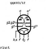
Please note the two caps from plate to grid, this is the usual way to eliminate C Miller by
neutralization in a pp topologie.
Kind regards,
Darius
http://frank.pocnet.net/index.html
QQE03/12
Hello ray_moth,
Originally #19 posted by ray_moth
Hi Darius,
I don't follow that. Triodes have significant Miller AFAIK, whether they're SE or PP. It's pretty well negligible for pentodes, though.
...
Please note the two caps from plate to grid, this is the usual way to eliminate C Miller by
neutralization in a pp topologie.
Kind regards,
Darius
http://frank.pocnet.net/index.html
QQE03/12
Attachments
Re: C Miller ? No Problem in PP !
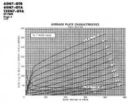
The 811 looks to be designed for +vg operation, I'm not surprised they looks like that - I know you picked that tube to prove your point, but most don't do that until the extremes of low plate voltages or high currents. Take a look at the 6L6 again in triode...+vg1 curves are given, and they are linear with respect to the -vg1 curves. Still useful.... Often it is a matter of scale on the graph that makes them look different as well.
And for SE? most times just a low-impedance source is necessary, and a follower works well here.
oldeurope said:Hi SY,
Maybe g2 glowing, maybe excessive cathode current ...
And a few dB headroom does not solve the blocking distortion problem.
Hello Boris_The_Blade,
For pentodes if it is possible to apply the g2 voltage I need.
I agree with the rest of your text, thanks.
Please note:
The triode changes its output characteristic at positive grid voltages.
See link. ...
Kind regards,
Darius
The 811 looks to be designed for +vg operation, I'm not surprised they looks like that - I know you picked that tube to prove your point, but most don't do that until the extremes of low plate voltages or high currents. Take a look at the 6L6 again in triode...+vg1 curves are given, and they are linear with respect to the -vg1 curves. Still useful.... Often it is a matter of scale on the graph that makes them look different as well.
oldeurope said:Please note the two caps from plate to grid, this is the usual way to eliminate C Miller by
neutralization in a pp topologie.
And for SE? most times just a low-impedance source is necessary, and a follower works well here.
Re: C Miller ? No Problem in PP !
I know, I know! It is a multivibrator!
oldeurope said:Hello ray_moth,
Please note the two caps from plate to grid, this is the usual way to eliminate C Miller by
neutralization in a pp topologie.
Kind regards,
Darius
http://frank.pocnet.net/index.html
QQE03/12
I know, I know! It is a multivibrator!
#42
Hello Boris_The_Blade,
See post #18.
Yes, I know that people don't want to hear this.
It is a physical effect that a triode becomes “transistor like”
at positive grid voltages with respect to cathode.
This does not mean they get non linear, they just loose the
typical triode characteristics. It is physics and is guilty for
all triodes without exception.
Since this is a disaster for some people, the moderators can make a
forum rule that this physical effect must be ignored here.
And don't forget to erase this thread.
BTW:
I am using this effect to make constant current sources using triodes.
See V9 in the here:
schematic
Kind regards,
Darius
Hello Boris_The_Blade,
Originally #42 posted by Boris_The_Blade
...
And for SE? most times just a low-impedance source is necessary, and a follower works well here.
See post #18.
Originally #42 posted by Boris_The_Blade
The 811 looks to be designed for +vg operation, I'm not surprised they looks like that - I know you picked that tube to prove your point, but most don't do that until the extremes of low plate voltages or high currents. Take a look at the 6L6 again in triode...+vg1 curves are given, and they are linear with respect to the -vg1 curves. Still useful.... Often it is a matter of scale on the graph that makes them look different as well.
...
Yes, I know that people don't want to hear this.
It is a physical effect that a triode becomes “transistor like”
at positive grid voltages with respect to cathode.
This does not mean they get non linear, they just loose the
typical triode characteristics. It is physics and is guilty for
all triodes without exception.
Since this is a disaster for some people, the moderators can make a
forum rule that this physical effect must be ignored here.
And don't forget to erase this thread.
BTW:
I am using this effect to make constant current sources using triodes.
See V9 in the here:
schematic
Kind regards,
Darius
Please note the two caps from plate to grid, this is the usual way to eliminate C Miller by
Sorry, you've lost me. What does a dual pentode with cross-coupled grid-plate capacitors have to do with triodes in PP?
eliminating C-Miller influence in a triode PP ...
Hello ray_moth,
The cross-coupled grid-plate capacitors eliminate C-Miller in a triode PP as well.
Kind regards,
Darius
Hello ray_moth,
Originally #45 posted by ray_moth
Sorry, you've lost me. What does a dual pentode with cross-coupled grid-plate capacitors have to do with triodes in PP?
The cross-coupled grid-plate capacitors eliminate C-Miller in a triode PP as well.
Kind regards,
Darius
#47
Hello SY,
thanks for telling that this is true.
Please note that it works in all classes, of course.
Kind regards,
Darius
SY said:... but has the limitation that it only works for stages kept strictly in class A.
Hello SY,
thanks for telling that this is true.
Please note that it works in all classes, of course.
Kind regards,
Darius
Re: #42
If you bother to look at the negative vg1 and positive vg1 curves together (the 811 is not a good example of this - the graph does not show a whole lot), like a 6SN7 , you'd see that the plate resistance does not change when going from negative to positive vg1 (as long as the tube isn't space charge limited), the negative and positive vg1 curves are parallel; hence a triode with +vg1 would not perform any better than -vg1 for a ccs, unless you are using the grid current to some advantage in the circuit. I'm not sure where you get 'transistor-like'...the plate resistance is a far cry from that, or even most pentodes - but the graphs can be deceiving.
SY, you have the patience of a saint!
oldeurope said:Hello Boris_The_Blade,
See post #18.
Yes, I know that people don't want to hear this.
It is a physical effect that a triode becomes “transistor like”
at positive grid voltages with respect to cathode.
This does not mean they get non linear, they just loose the
typical triode characteristics. It is physics and is guilty for
all triodes without exception.
Since this is a disaster for some people, the moderators can make a
forum rule that this physical effect must be ignored here.
And don't forget to erase this thread.
BTW:
I am using this effect to make constant current sources using triodes.
See V9 in the here:
schematic
Kind regards,
Darius
If you bother to look at the negative vg1 and positive vg1 curves together (the 811 is not a good example of this - the graph does not show a whole lot), like a 6SN7 , you'd see that the plate resistance does not change when going from negative to positive vg1 (as long as the tube isn't space charge limited), the negative and positive vg1 curves are parallel; hence a triode with +vg1 would not perform any better than -vg1 for a ccs, unless you are using the grid current to some advantage in the circuit. I'm not sure where you get 'transistor-like'...the plate resistance is a far cry from that, or even most pentodes - but the graphs can be deceiving.
SY, you have the patience of a saint!
SY said:This is true, it's outlined in Crowhurst's "Understanding Hifi Circuits" (sorry, that's a book that has to be bought)
No it doesn't. It's on Pete Millet's site: Download. (Although I didn't find it none too useful being that it's mainly about stabilizing amps with way, way, way too much gNFB -- which was SOP for every "Big Box" design of the times and ever since. Actually, Crowhurst knew better than that, but he did work as a design consultant for the "Big Box" manufacturers.)
Originally posted by oldeurope
Please note that it works in all classes, of course.
Cross coupling does not work for any Class AB operation since one tube goes into cutoff, and disappears from the circuit. Once that happens, there is no more feedback to reverse bootstrap the Crt of the opposite tube, and Cmiller returns just as if there were no reverse bootstrapping at all.
Originally posted by oldeurope
Sorry we live in the internet age. Do we have to pay for knowledge here?
No, of course not. Look around and you can probably find a torrent somewhere where you can gack Jones' book. There are lots of netizens with no regard for the IP rights of others. Can you live with your conscience though?
Originally posted by oldeurope
An AB2 output tube driven n Volts positive by a cathode follower is equal to
AB1 with increased g2 Voltage. The additional g2 voltage is n Volts multiplied by µ(g2).
This is the reason why AB2 is not necessary in a pentode topology.
You don't need a cathode follower to drive a pentode.
Make sure, by the usual and traditional means that the stage never needs a grid drive voltage
more than say minus 5V. Same result, without follower.
In this case add 5V x µ(g2) to the traditional g2 DC level.
You don't need a follower, that's fine isn't it?
Not necessarily, with types such as the 1624 and the 814, you will get tinywatts at some ridiculous voltages if you keep 'em in Class AB1. There simply isn't enough current available at Vgk= 0V. Other types, such as the 807, can produce lotsawatts if you go Class AB2. The question is: can you get that Vsgsg high enough? For types like those mentioned here, you can't since the screen voltage rating is rather low in comparison to allowable Vpp. Secondly, you might be putting it well into red plate territory with a Class AB1 loadline even if you could get that screen voltage high enough without causing a flash-over.
As for never needing cathode follower drivers, never say never. In two designs I did, an 807 amp and a 6BQ6GTB amp, both included CF grid drivers. The 807 design used 6SL7s as the phase splitter. The 6SL7 runs at some very low plate currents, and doesn't have the drive capability.
For the 6BQ6GTB design, the phase splitter was cascoded 6BQ7s. Cascoding raises the effective r(p) tremendously, and it needs to work into a Hi-Z load if the frequency response isn't to fall apart completely. That, too, needed CF grid drivers in order to keep the cascode's HF response.
In both cases, the grid drivers greatly improve overdrive performance in that both designs run into OPT core saturation before the finals actually clip since these can transparantly slip into ClassAB2 when that fast rising transient comes along.
technical forum rules
@SY #49
Ok, SY,
I added this one : "Neutralisation only in class A allowed."
To the forum rules.
@ Boris_The_Blade #50
No need for a discussion, please look at the technical forum rules.
Ups, what is this? Is it a transistor?
Kind regards,
Darius
@SY #49
Ok, SY,
I added this one : "Neutralisation only in class A allowed."
To the forum rules.
@ Boris_The_Blade #50
No need for a discussion, please look at the technical forum rules.
Ups, what is this? Is it a transistor?
Kind regards,
Darius
Attachments
Miles, thanks for the correction- Pete comes through again!
Regarding the AB/B compensation issue, I believe your reasoning is correct. I don't know exactly what Darius is thinking, but it may be that even when the tube on one side of the p-p is cut off, the transformer is still swinging, and this is indeed true of an ideal transformer.
Unfortunately, that ceases to be true for real transformers right at the frequencies when you need it to deliver charge. Thus my suggestion for Darius to actually rig this up on a test bench and test his assumptions. I learned about it the hard way when I got too enthusiastic about the neutralization idea (right after I read the Crowhurst book back in the late '70s). I couldn't get my amp to stabilize above a couple of watts and spent days tearing my hair out trying to figure out why.
SY said:Miles, thanks for the correction- Pete comes through again!
S'OK
Originally posted by SY
Thus my suggestion for Darius to actually rig this up on a test bench and test his assumptions.
Don't do that. Facts are such confusing things.

hey-Hey!!!,
The system running AB is still going to get this positive FB that's being used to neutralize Miller. How well it does this is entirely dependant on the OPT. Some are clearly better at this than others.
While operating with ont tube cut off, the other side of the primary is an inverting 1:1, and it is delivering this signal through the small cap to the conducting tube. Ironically, the higher the output Z of the driving stage, the more positive FB is being dlivered( while needing it the most ). It works with best balance in Class A...and for PP, balance is not to be understimated...
cheers,
Douglas
Neutralization IS positive feed back intented to cancel negative feed back introduced by inter electrode capacitances, specially when exacerbated by Miller effect.
In RF applications, phase shift may be such that oscillations occurs, usually out of band.
Of course, OPT can do that also if they introduce too much phase shift near or over higest frequency of interest .... even without any "explicit" NFB.
Yves.
In RF applications, phase shift may be such that oscillations occurs, usually out of band.
Of course, OPT can do that also if they introduce too much phase shift near or over higest frequency of interest .... even without any "explicit" NFB.
Yves.
I have never had any luck using the cross coupled caps for neutralisation.
I couldn't even get it to work in a front end diff amp. Every time I've tried it I ended up with an oscillator instead of an amplifier.
A case of my practice not being up to the standard of the theory - well maybe BUT "that did'nt work - lets do it some more" is an engineering practice I try to avoid. I'll leave that practice to the polititions of the world.
Cheers,
Ian
#59
Hi Ian,
this is why in this forum neutralisation is forbidden.
I added this one to the “technical forum rules”.
Kind regards,
Darius
BTW: I am using neutralisation successfully in sound and radio frequency stages. No problem for me.
Originally #59 posted by gingertube
I have never had any luck using the cross coupled caps for neutralisation.
I couldn't even get it to work in a front end diff amp. Every time I've tried it I ended up with an oscillator instead of an amplifier. ...
Cheers,
Ian
Hi Ian,
this is why in this forum neutralisation is forbidden.
I added this one to the “technical forum rules”.
Kind regards,
Darius
BTW: I am using neutralisation successfully in sound and radio frequency stages. No problem for me.
- Status
- This old topic is closed. If you want to reopen this topic, contact a moderator using the "Report Post" button.
- Home
- Amplifiers
- Tubes / Valves
- Direct-coupled cathode/source follower driver in PP?