I have a Marantz 8B in for major repair. It's been hot and I'm in the process of recapping it and replacing out-of-spec resistors. I want to replace the rectifier diodes as well. Suggestions for the best component appreciated. I'll replace the selenium bias rectifier with a 1N4007.
If you use a 1N400* then as the voltage drop is considerably less, you must select a new value for the bias voltage resistor R20.
1N4007 is ideal for the half wave bridge rec. 1N4003 is more than high enough voltage rating for the negative bias supply.
1N4007 is ideal for the half wave bridge rec. 1N4003 is more than high enough voltage rating for the negative bias supply.
Hello,
A couple years back I built an 8B clone using ST70 transformers. The amp sounded wonderful. In that thread Eli gave me the needed information to build the power supply. Check post #11. The title of the thread is: Marantz 8b power transformer
It was dead quiet.
Kevin
A couple years back I built an 8B clone using ST70 transformers. The amp sounded wonderful. In that thread Eli gave me the needed information to build the power supply. Check post #11. The title of the thread is: Marantz 8b power transformer
It was dead quiet.
Kevin
Use 1N400n series diodes? No, no, a thousand times no! The 1N400n series parts are nasty, noisy, trash. Use UF400n diodes in place of the corresponding 1N400n parts. The difference in cost is pennies, but the difference in switching noise levels is HUGE.
I've long since forgotten what I said in the thread mentioned by m2racer.
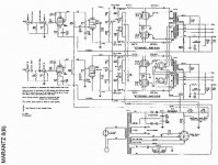
Take a close look at the 8B schematic. It employs stacked diode pairs in a Greinacher doubler B+ PSU, just like the H/K Cit. 2 does. Contact Jim McShane and buy the same diodes he puts into a "Deuce". Buy the film snubber too. If replacement PSU caps. have not already been purchased, talk to Jim about increasing the value of the parts in the doubler stack. If you do increase the cap. value in the doubler stack, buy Jim's NTC inrush current limiting thermistor kit. What's going on in an 8B is quite similar to what's going on in a "Deuce". We are talking about 2 of the very finest "vintage" amps ever offered to the public.
I've long since forgotten what I said in the thread mentioned by m2racer.
Take a close look at the 8B schematic. It employs stacked diode pairs in a Greinacher doubler B+ PSU, just like the H/K Cit. 2 does. Contact Jim McShane and buy the same diodes he puts into a "Deuce". Buy the film snubber too. If replacement PSU caps. have not already been purchased, talk to Jim about increasing the value of the parts in the doubler stack. If you do increase the cap. value in the doubler stack, buy Jim's NTC inrush current limiting thermistor kit. What's going on in an 8B is quite similar to what's going on in a "Deuce". We are talking about 2 of the very finest "vintage" amps ever offered to the public.
Attachments

rkoonce,
Somehow a couple years back I said or did something to tick Eli off. But when he was speaking to me he was very helpful and maybe a little too patient. I've learned a lot since then and don't need to ask so many stupid questions but here is what Eli recommended back then:
Parallel 2X UF5408s with high WVDC 10 nF. caps. and use the assemblies on the ground side of the bridge. Use 2X 600 PIV Schottky diodes on the "hot" side of the bridge. The rail will be dead quiet, while costs are contained. Insert a CL150 negative temperature coefficient (NTC) inrush current limiting thermistor between the Schottkys and the PSU filter, to slightly "soften" B+ start.
SS or vacuum for the rectification, CLC filtration is the way to go. If you use a large valued 1st filter cap., install a "hash" filter (as I have recently described more than once) between said cap. and the choke.
Mount ferrite beads on the heater winding leads, to protect against noise sneaking into the signal path, via the heater supply.
Panasonic (Matsushita) makes excellent 'lytics. Buy 'em from DigiKey. Nichicon and United Chemicon also produce suitable stuff.
The one thing I can say for sure is he was right. The power supply was black quiet and the amp sounded wonderful!
Marantz 8B again
I got the amp recapped and I replaced any resistors which were more than 5% out of spec and it seems to behave as far as the power supply, but the amp doesn't pass a signal on either channel. I'm running it at reduced input voltage for testing which produces about 275V B+. I inject a 1V signal and I can follow it through to pin 2 on the 6CG7 where I measure about 35VAC, so good gain from the Input tube. I get no signal in pin 7. B+ appears where it should. The meter was replaced with one from VAC and I was told it has an internal shunt. I get no meter deflection with bias adjustment. I do measure B+ on both meter terminals. Suggestions appreciated.
I got the amp recapped and I replaced any resistors which were more than 5% out of spec and it seems to behave as far as the power supply, but the amp doesn't pass a signal on either channel. I'm running it at reduced input voltage for testing which produces about 275V B+. I inject a 1V signal and I can follow it through to pin 2 on the 6CG7 where I measure about 35VAC, so good gain from the Input tube. I get no signal in pin 7. B+ appears where it should. The meter was replaced with one from VAC and I was told it has an internal shunt. I get no meter deflection with bias adjustment. I do measure B+ on both meter terminals. Suggestions appreciated.
There should be no signal on pin 7 as it is dedcoupled with a 330nF capacitor, C6. Pin 2 should have signal on it.
R31 open circuit = No supply to the anodes of the phase splitters.
If you have signal on the control grids, by default you will have signal on the anodes.
If you have signal on the control grids, by default you will have signal on the anodes.
1N4007 diodes are perfectly adequate and indeed exceed the specification of the older type silicon diodes (35-1035). UF4007, if you have some, will work but we are not talking excess current and there is plenty of absorption for RF noise, that any valve amplifier will not even see. It is however, good practice to place a 1nF 1kv capacitor across each diode, anode to cathode. That will aid voltage spike sharing. If you are using a solid state amplifier that is susceptible to mains born noise, a UF type diode is preferable to a 1N type, for noise issues.
May I suggest that changing values of the capacitors could have a detremental effect on the quality of sound reproduction. It is always best to make use of the original design engineers' expertise. after all, they know better than most DIY'rs.
May I suggest that changing values of the capacitors could have a detremental effect on the quality of sound reproduction. It is always best to make use of the original design engineers' expertise. after all, they know better than most DIY'rs.
May I suggest that changing values of the capacitors could have a detremental effect on the quality of sound reproduction. It is always best to make use of the original design engineers' expertise. after all, they know better than most DIY'rs.
That does not hold, in the case of doubler stack parts. Back in the day, parts with the high volumetric efficiency and modest cost of the current inventory were simply unavailable. Believe me, Hegeman and Marantz would have used lots of capacitance in their doubler stacks, if given the opportunity.
A refinement to the PSU topology of doubler, choke, and reservoir cap. is to insert a "hash" filter LC section made from a high current RF choke and a 1000 pF. mica or NPO ceramic cap. between the doubler stack and the main filter choke. "Hash" from several sources might sneak past the winding capacitance of the choke. That can't happen, when the filter made from RF parts is installed and a "black background" is the result. FWIW, large caps. in the doubler stack generate "hash" in the process of crushing the ripple fundamental. Consider the ripple waveform and Fourier's Theorem.
Oh dear. Seems clarification is in order here.
This amplifier is or rather was, rated as one of the best in its day. Why change something that is that good?
Doubler stack. What is that? Do you mean a full wave bridge rectifier that will produce 1.414 times the RMS voltage input? That is not a double. A doubler uses a series capacitor, a shunt diode and a forward diode followed by a tank capacitor..
Or two diodes in series to double the working voltage of a single diode.
My philosophy has always been, If it ain't broke, you can't fix it.
A theorem is theory after all!
Please refer to the uploaded Marantz 8B schematic. The B+ PSU is a "full wave" voltage doubler. Notice the cap. stack. Considerable benefit comes from increasing the capacitance in the doubler stack. When the amp was new, high value parts that fit in the available space could not be sourced. Modern etching techniques have GREATLY increased the capacitance per unit volume of electrolytic caps. and have done so at reduced cost. 🙂 With care, that which was very good, to begin with, can be made better. 😀
Attachments
R31 open circuit = No supply to the anodes of the phase splitters.
If you have signal on the control grids, by default you will have signal on the anodes.
Well, see, there's the thing. I have signal on pin 2 and none on pin 7 of the 6CG7. I have anode voltage and the tubes are passing 12 mA of current through a common 13K cathode resistor. I have no signal on the anodes. What's up with that? The tubes both test fine in my emission tester. Any constructive suggestions will be appreciated.
Amateur here, maybe pointing out the obvious? Do you have a signal generator? If you do, with the amp off and 6BH6 and 6CG7 removed, apply an AC signal at pin 5 of 6BH6. Then trace it through R6, C5, and R5. Then disconnect C5 from ground, and disconnect feedback connection, then finally lift one side of R7. You're looking for a loss of signal between pin 5 of 6BH6 and pin 7 of 6CG7, yet you have signal on pin 2 of 6CG7. You shouldn't need either tube installed or power on to find this problem. Would love to be of help?
Amateur here, maybe pointing out the obvious? Do you have a signal generator? If you do, with the amp off and 6BH6 and 6CG7 removed, apply an AC signal at pin 5 of 6BH6. Then trace it through R6, C5, and R5. Then disconnect C5 from ground, and disconnect feedback connection, then finally lift one side of R7. You're looking for a loss of signal between pin 5 of 6BH6 and pin 7 of 6CG7, yet you have signal on pin 2 of 6CG7. You shouldn't need either tube installed or power on to find this problem. Would love to be of help?
There's another thread on this subject and here's what I was told there:
No signal and or low DC voltage on pin 7 or the non-driven grid is normal. The reason is the grid is at AC ground thru C6. The DC voltage is low because the all of the voltage is coming from R7 which is a 1M resistor, very little current and your meter/scope loads it down unless you use a very high imp. meter.
Thanks for your input.
Ah, I wondered about C6 and would it be a short to ground. But I think I just learned something? Is the signal transferred from the upper tube (grid pin 2) to the lower tube via the coupled cathodes? And is that the mechanism that throws it out of phase? If that is the case what is the purpose of all those resistors and caps between R6 and R7? I recognize R7 as a grid resistor. And is the lower tube a grounded grid then?
- Status
- Not open for further replies.
- Home
- Amplifiers
- Tubes / Valves
- Diodes for Marantz 8B