Neither. It will be something like 925V, which you may want to double in case of mains transients. This assumes that the 660V is an RMS value - the usual way that transformers are specified.
Good point, those are RMS values, hadn't thought of that. I see a good selection of 1200v rated parts on Mouser so i should be able to find something suitable.
Thanks,
Mark
Thanks,
Mark
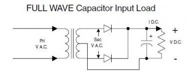
This is a full wave rectifier, not a bridge.
Diode will see twice the peak voltage, which in this configuration is 1.4142*330VAC , so twice 467VDC = 934V
A nominally 1000V diode, such as popular 1N4007 customarily stands this, because of course it's made with some extra safety margin.
Diode will see twice the peak voltage, which in this configuration is 1.4142*330VAC , so twice 467VDC = 934V
A nominally 1000V diode, such as popular 1N4007 customarily stands this, because of course it's made with some extra safety margin.
EM513 = 1600v 1A
EM518 = 1800v 1A
usual method in such case however is to connect two diodes in series
2 x 5408 = 2x1000v 3A
EM518 = 1800v 1A
usual method in such case however is to connect two diodes in series
2 x 5408 = 2x1000v 3A
I'd suggest a robust surge suppressor after the mains fuse and before the transformer primary. For example this TransZorb is rated 1500 watts, costs less than a dollar, and protects your 1800 volt diodes in the secondary circuit by popping the mains fuse. Connect a 22 kiloampere MOV such as this one in parallel, for extra piece of mind. A voltage surge is clamped, the (enormous) clamping current blows the fuse, which protects the downstream electronics like your fragile 1.8 kilovolt diodes.
_
_
Last edited:
EM513 = 1600v 1A
EM518 = 1800v 1A
usual method in such case however is to connect two diodes in series
2 x 5408 = 2x1000v 3A
Or BY228 = 1500V 3A 😎
Mona
I'd suggest using 2x 1N4007 or UF4007 in series for each diode (assuming current rating is fine), without any balancing caps or resistors. Although 1N4007 is 1kV PIV rated, and may have some margin, the AC mains could be 10-15% off the rated primary voltage of your transformer, as you haven't really identified that side of the equation.
Using 2 series diodes of the same type/batch should give you sufficient extra PIV (not 2x PIV, but certainly a good percentage of that). And it also reduces the off-state diode capacitance, and so alleviates noise egress from the PT side of the diodes.
A compromise on the brickwall primary side transient protection suggested by Mark would be a smaller MOV alone placed across the primary winding. Such a MOV would clip any primary winding induced voltage transient induced by a power switch turning off. If you feel as if your equipment needs protection from high energy transients/surges coming in from external mains AC (eg. lightning strike, or a HV line falling on an LV line), then I suggest that protection is best located at your switchboard, or in a local power board that also protects other audio gear as well.
All my equipment is behind a mains filtering unit so i should be fairly well protected against spikes.
I am very tempted to use a rectifier tube instead, i tried an 83 mercury rectifier and it seems to work just fine, datasheet specs 1550v inverse voltage, 550v rms peak per plate limit, and 100ma is less than half its rated current. Unless i am missing something it seems ideal for the job, and looks pretty too 🙂
I am very tempted to use a rectifier tube instead, i tried an 83 mercury rectifier and it seems to work just fine, datasheet specs 1550v inverse voltage, 550v rms peak per plate limit, and 100ma is less than half its rated current. Unless i am missing something it seems ideal for the job, and looks pretty too 🙂
Did you PSUD2 the repetitive peak, and hot start peak current levels to check against the diode data sheet?
A small mov is still a good idea to handle spike on PT side of mains switch.
A small mov is still a good idea to handle spike on PT side of mains switch.
Yes i did, was not a trivial task either as i ended up having to use a 2uf filter cap and a large resistor to keep things in check. Gone off the idea of rectifier tubes now, too many limitations and downsides without any positives, other than looking pretty. Fair to say the novelty has worn off.
Back to looking as solid state options, can anybody explain the pros and cons of capacitance and reverse current when looking at diodes and rectifiers? I am assuming the lower the two, the better.
Cheers,
Mark
Back to looking as solid state options, can anybody explain the pros and cons of capacitance and reverse current when looking at diodes and rectifiers? I am assuming the lower the two, the better.
Cheers,
Mark
Some people solder a capacitor directly across the terminals of each diode in a bridge rectifier. Four diodes, four capacitors. I would imagine those folks don't care about diode capacitance at all, since Cacross >> Cdiode.
For those who use a CRC snubber between the transformer and the rectifier diodes, it's important to know the value of Cdiode, in order to set the snubber Cx >> Cdiode. Fortunately the vast majority of diodes are less than 1.5nF and so the "recommend starting point" Cx=10nF, is indeed much greater than Cdiode. Whew, a design decision avoided! In the rare cases when Cdiode is more than 1.5nF that's not the end of the world, it just means you need to select a larger Cx and a larger Cs. Google for Quasimodo test jig to learn more.
Reverse current would not be an issue unless it is a non-negligible fraction of the power supply output load current. I wouldn't pay attention to the reverse current rating unless Ireverse > (Ioutput / 50). But this has never happened, at least, not to me.
For the diodes i am looking at we are talking 8-20pf so i assume its not worth worrying about then.
I usually do fit snubbers across the secondary as i built my own cheapomodo for testing. In this case i decided against it due to the voltages involved, having enough trouble getting diodes to work never mind snubbers 🙂
I usually do fit snubbers across the secondary as i built my own cheapomodo for testing. In this case i decided against it due to the voltages involved, having enough trouble getting diodes to work never mind snubbers 🙂
For simple power supplies, ss diodes are equally simple to use.
For audio applications, where people spend extra effort to alleviate 'noise and spikes' that get past the power supply and can be 'seen' on the output signal then that requires a little more attention to detail.
Diode current is meant to stop when voltage reverses, but diode capacitance and reverse current let through 'noise' currents that then has a chance to get past the power supply filtering and out to B+ (and then eg. via output transformer capacitance to speaker leads).
Reverse current can happen at the moment of reverse biasing, in which cast the faster diodes (such as UF4007) are better. Reverse current that is forced by reverse bias voltage is very temperature and voltage dependant.
Diode capacitance lets through the dV/dt character of the transformer winding voltage. Unfortunately, winding voltage is not always nicely sinusoidal, but includes many harmonics from the mains AC, as well as a substantial step in voltage due to current stopping at diode turn off. Diode capacitance increases with diode current rating, so using the lowest current rated diode helps. Using two diodes in series, halves the total diode capacitance, so that helps. Using a secondary winding snubber helps by trying to smooth out the voltage at the time of diode turn off.
SS diodes induce a 'harder' turn off than valve diodes, and so often don't exhibit the noise/spikes that are often observed at the time of diode turn-off when looking at a signal waveform.
Last edited:
- Status
- Not open for further replies.
- Home
- Amplifiers
- Power Supplies
- Diode reverse voltage w/center tapped transformer