For analog switches, correction application is key.
It was always amusing to me that the well-liked Hafler 915 JFET preamp used the often disrespected CD4051 as a source selector.
🙂
I thought it was a nice sounding preamp.
mlloyd1
It was always amusing to me that the well-liked Hafler 915 JFET preamp used the often disrespected CD4051 as a source selector.
🙂
I thought it was a nice sounding preamp.
mlloyd1
For analog switches, correction application is key.
It was always amusing to me that the well-liked Hafler 915 JFET preamp used the often disrespected CD4051 as a source selector.
🙂
I thought it was a nice sounding preamp.
mlloyd1
Often its the implematation, that matters. If the CD4051 does not switch the signal itself, but only drives the real switch, than anything is fine. But i cant imagine, that the CD4051 switches the signal directly 😉.
Often its the implematation, that matters. If the CD4051 does not switch the signal itself, but only drives the real switch, than anything is fine. But i cant imagine, that the CD4051 switches the signal directly 😉.
The CD4051 most deferentially does switch the signal....
http://www.hafler.com/pdf/archive/Series915_preamp_man.pdf
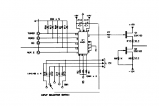
Look at page 22, U1 is the 4051 and the Tuner, Video,CD,Phono/Aux1, and AUX2 are ALL connected directly to and switched by the IC. The signals are inputted on pins 1,5,14,14 and 15 and exit on pin 3
The CD4051 most deferentially does switch the signal....
http://www.hafler.com/pdf/archive/Series915_preamp_man.pdf
Look at page 22, U1 is the 4051 and the Tuner, Video,CD,Phono/Aux1, and AUX2 are ALL connected directly to and switched by the IC. The signals are inputted on pins 1,5,14,14 and 15 and exit on pin 3
You're right. I cant tell you why, but i had thd of over 12% under 1k with the cd4051, but perhaps i need a better psu for this chip.
I will try both, the relay way and once again the cmos way with a better psu.
Thank you for pointing this out.
Often its the implematation, that matters. If the CD4051 does not switch the signal itself, but only drives the real switch, than anything is fine. But i cant imagine, that the CD4051 switches the signal directly 😉.
Nevertheless, with some smart circuit design, these types of switches can be pretty much invisible, audio-wise. If for instance you use them to switch the inv inputs of opamps in inverting mode, there's just mV across a switch. Prety invisible.
This type of switch can even be found in well-regarded distortion analyzers, switching the signals and attenuators.
Jan
You're right. I cant tell you why, but i had thd of over 12% under 1k with the cd4051, but perhaps i need a better psu for this chip.
I will try both, the relay way and once again the cmos way with a better psu.
Thank you for pointing this out.
LinuxGeek,
If you intend to give it another go, I would try and build it exactly as in the Hafler 915 data sheet, relevant subsection picture attached here as it's known to work. Note the load on pin 3 looking at the gate of the jfet is many millions of ohms, meaning the switch will develop virtually no voltage across it. You can replace the jfets with LSK170 or 2SK170 or LSK389. And you can even run the jfet buffer from the same +9/-9 rails used for the chip. In fact you can try it with two 9 volt batteries as a quick mock-up. Like the B1 buffer you may wish to add a 1k safety resistor at the output, to prevent blowing the jfet in case you short the output, dc decoupling unlike the B1 is optional for this circuit, DC offset will depend on the jfet matching, if it was me I would use it. Keep the connection between pin 3 and the gate of the jfet as short as possible it's practically floating when switching between channels. I found some pictures of the inside of the Hafler 915 online so you can get an idea of a "known good" layout. I would be interested to know how it sounds.
As a side note, judging by your screen name, it may interest you to know I an typing this on my CentOS home desktop. At my place of work we operate a relatively small 3mile in diameter particle accelerator (the RHIC) and the data from this collider is processed on our 20,000 cpu cluster all running Scientific Linux, which is also my work desktop.
Attachments
Guys, thank you all for your help. Today i realized my problem. My older attempts were wrong from a design perspective. I never "sank" or how to call it the not selected signal. All signals, that are not selected should go to a high impendance resistor to sink the signal. I did not do that in my former designs.
So the signals, that were not selected were floating and this was all that caused distortions and also crosstalk with the adg1414. I will go back to breadbording and correct my designs. I will once again try the cd4066, cd4051 and the adg1414.
Only my old relay will not benefit from this treatment.
I will report as soon as i tried cmos way the proper way.
For the cd4066, that was still on one of my beradboards, the distortion went back from around 12% at 1k to just 0,15%. Still too high for me, but i think the adg1414 could do the trick or perhaps the cd4051, i will try.
What model number of relays did you try?
Not all are for signal levels.
I used a NEC MR82, it was nit the cheapest one, but its intended for high load i think. Perhaps this was the problem.
As a side note, judging by your screen name, it may interest you to know I an typing this on my CentOS home desktop. At my place of work we operate a relatively small 3mile in diameter particle accelerator (the RHIC) and the data from this collider is processed on our 20,000 cpu cluster all running Scientific Linux, which is also my work desktop.
I want tooo.... 20.000 should be fine. I need to render sime molecules next month. This will stall our servers for 2 weeks. Yours should make it a bit faster...
But there are always good and bad sides.
Two weeks very lazy work 😀
Last edited:
Hello,
I'm trying to use the electronic component ADG1414. But it doesn't work... I use a clk of 1 MHz. (I also tried a clk of 1, 10, 100 Hz). I have this datasheet :
http://www.analog.com/media/en/technical-documentation/data-sheets/ADG1414.pdf
On the page 8, we have the timing diagram. I respect the diagram on the figure 2 with the reset signal driven low.
I don't understand why it doesn't work. Can you tell me our working frequency ? Or if i have made a mistake ...
I have an other question :
What is your package (LFSCP, TSSOP ...) ? I have the package LFSCP .
Thank you very much and i'm sorry for my english, I'm french...
Have a nice day !
Hello !
I'm trying to use the ADG1414. But it doesn't work. I respect the timing diagram on figure 2 of the page 8 of this datasheet : http://www.analog.com/media/en/technical-documentation/data-sheets/ADG1414.pdf. I have also put the reset signal low.
I tried to use it with a frequency of 1000 Hz, 100 Hz 10 Hz or 1 Hz. In any case, the electronic component doesn't work.
Can you tell me if i have made a mistake and what package do you have ? I have the package LFSCP.
Thank you very much and i'm sorry for my english , i'm french...
Have a nice day.
@leo
First, I hope you have a probe to check that the device is properly soldered. I used the TSSOP as its easier to work with. I put one on an adapter board, TSSOP-->DIP which makes it much easier to probe.
Which microprocessor are you using -- mine is just an Arduino and seems to work fine.
First, I hope you have a probe to check that the device is properly soldered. I used the TSSOP as its easier to work with. I put one on an adapter board, TSSOP-->DIP which makes it much easier to probe.
Which microprocessor are you using -- mine is just an Arduino and seems to work fine.
i'm not linuxgeek, but ...
i heard and liked the hafler 915 i heard long ago when it was introduced. i would have bought a used 915 to keep around as a stand-by preamp, but never found one for sale at a price i'd consider.
some years ago, i threw together a "hafler 915 clone" as an interim preamp and liked it enough to keep it around to serve between my various experiments. i like the way it sounded too, but i've never measured it or "beat up" on it hard (for example, your earlier comments about not overloading the switch are valid).
my first experiment used 74hc4051/52 into opa627. that worked well. later, i used some maxim part (max351 maybe? it's been a while) into a buffer using 2sk163 with 2sc1775 as cascodes. i liked that the maxim part could use the +/-15v rails, and so presumably (again, not verified by testing) would have lower distortion.
mlloyd1
LinuxGeek,
... I would be interested to know how it sounds ...
Thank for your answer.
I think i will try with an arduino. I have a new question : Did you put a capacitor near the reset pin to supply the numeric part of the ADG1414 ? How far from the reset pin of the ADG1414 is this capacitor?
Do you have put other electronic component to work fine your ADG1414 ?
If you can send me a picture, it will be very nice to you.
Thank you very much.
Have a nice day !
The ADG1414 has the lowest switch resistance, thus lowest THD with rail voltages near +/-15V
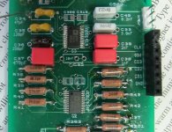
This is a prototype of a switchable filter which uses 3 of the ADG1414's. Got a little careless with the soldering pencil and melted the molex connector! (works nicely, however.)
This is a prototype of a switchable filter which uses 3 of the ADG1414's. Got a little careless with the soldering pencil and melted the molex connector! (works nicely, however.)
Attachments
i thought I was the only one that did that!
😛
mlloyd1
😛
mlloyd1
... Got a little careless with the soldering pencil and melted the molex connector! (works nicely, however.)
- Status
- Not open for further replies.
- Home
- Source & Line
- Analog Line Level
- Digitaly controlled input selector advice