I have a few comment for the board layout. You should switch the connections on the 100nf decoupling capacitors to make the distance between the chip and the caps as small as possible.
You should also add decoupling capacitors on the digital supply, as shown in the PGA2310 datasheet.
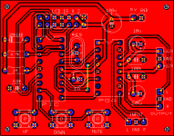
You can see my board here: http://electronics.dantimax.dk/Kits/Foto/ChipVol1-3.495_400.jpg
The 100nF digital decoupling cap is on the solder side.
Best regards,
Mikkel C. Simonsen
You should also add decoupling capacitors on the digital supply, as shown in the PGA2310 datasheet.
You can see my board here: http://electronics.dantimax.dk/Kits/Foto/ChipVol1-3.495_400.jpg
The 100nF digital decoupling cap is on the solder side.
Best regards,
Mikkel C. Simonsen
metal said:Of course you can't share any thing.
Isn't that what I just did? 🙂
My schematic is available at the website, where you can also see the board layout - I don't think I have to share more than that... 😉
Best regards,
Mikkel C. Simonsen
hi
metal:
thanks for the comments.
i will change the connector for the lcd and add some caps in the 5volts supply.
mcs:
thanks
i will switch the connections of the decoupling caps.
anymore suggestions?
metal:
thanks for the comments.
i will change the connector for the lcd and add some caps in the 5volts supply.
mcs:
thanks
i will switch the connections of the decoupling caps.
anymore suggestions?
Hello
Nice PCB, well done, I don't think you have to add modifications any more, it is good for now, coupling caps, LCD connector....
BTW, please create PDF files for PCB layout, schematic, components overlay, and silk screen.
Thanks
Nice PCB, well done, I don't think you have to add modifications any more, it is good for now, coupling caps, LCD connector....
BTW, please create PDF files for PCB layout, schematic, components overlay, and silk screen.
Thanks
Nice work guys.
What about adding an input buffer,as this is what the PGA datasheet has to say....... "It is important to drive the PGA2310 with a low source impedance. If a source impedance of greater than 600Ω is used, the distortion performance of the PGA2310 will begin to degrade."
Please see here for an implementation...http://www.mhennessy.f9.co.uk/preamp/analogue_research.htm
And yes if you could add code for remote control,would be just great.
Keep it going.
Cheers.🙂
Well done 🙂
Thanks HAU.
Can you please submit a file in PDF format containing of full schematic, PCB, bill of materials, and Silkscreen.
Regards
Thanks HAU.
Can you please submit a file in PDF format containing of full schematic, PCB, bill of materials, and Silkscreen.
Regards
hey guys, for those that are waiting for PICS chips from me. Microchip only allows me to snag a few a week so its gonna be a little bit longer then i thought.
Hi, sorry for the previous post. Well I am a student doing a Digital Hearing aid project. I am using a PIC12F683 microcontroller(With no I2C master function) together with a TDA7316 digital controlled Equalizer. I can't seem to make the 2 devices communicate with each other. Is it possible to do I2c communication Manually? and if so, does anyone have any useful asm source codes? Thank you so much.
G4ME said:hey guys, for those that are waiting for PICS chips from me. Microchip only allows me to snag a few a week so its gonna be a little bit longer then i thought.
I certainly hope you're not abusing their sample program- that's the sort of thing that screws things up for the rest of us...
- Status
- Not open for further replies.
- Home
- Amplifiers
- Chip Amps
- Digitally Controlled Volume, Tone IC ??