If you guys are still looking for PIC chips, i have a bunch of 877A's (and other chips, as free samples are well you know free) and will be willing to trade them for code/programer.
Hit me up via email or AIM at Suspectno6
Hit me up via email or AIM at Suspectno6
Hi, i have a similar plan and maybe the same problems.
I like to build a digital controlled equalizer and mixer.
This chips from ST semms to fit perfect except to one aspect. It has speaer outputs.
I like to have just a stereo out with line level.
http://www.st.com/stonline/products/literature/ds/9837/TDA7416.pdf
The problem is maybe that i don't know what line level is. I'm more firm in digital than analog wich is more or less voodoo for me. 🙂
Is the speaker output a problem if i just want to feed the output signal to a normal stereo Amp?
Well i am at the beginning of my searching for the right parts. Maybe this chip is cmpletely junk. Unfortunately i will not recognize that for my own... 😉
Car audio sounds a bit like low-fi.
National has great chips too. But thy are mostly not digitally controllable whis is essential for me.
Maybe it would make sense to split the whole job to many chips.
Input Mixer, Equalizer (spectrum analyzer would be cool) and volume controll. And if it would usefull a pre-amp.
All has to be digitally controllable.
I would really apologize if anyone has a tip for me.
PS: I want to controll the appliance with this cool 'buttons and sliderders' 🙂
http://www.qprox.com/
Metal, i can't find the Chips you posted from ST. Are they maybe discontinued?
ST has sone other great things but i don't know how good they are. :-/
ST has sone other great things but i don't know how good they are. :-/
Metal:
I would be very interested in hearing what you did with the pga's, i have a whole bunch of them, PKS was kind enough to trade me some too..
did you open a thread on the project? i have access to pic16f84's and programmers for a few more weeks, and would very much like to make the best of that time..
btw, nice to see there are more xtreme metal lovers on this forum.
I was beginning to feel a bit lone here.
Hi demogorgon
The code for PGA2310 and PIC16F84A is ready to go several weeks ago, it took me 2 weeks to write a really good code, but I have not drawn the schematic yet, cause I finished exams yesterday. In deed the code have to be tested to make sure the timing constraints of the LCD and serial communication with the PGA are fine.
I will postpone the TDA7315 project untill I finish the PGA2310 schematic and PCB design. In parallel I will be working on some I2C stuff, untill I understand it very well.
Hey, for the metal fans www.hdpvids.com lots of videos 😉
Last thing to say, this thread will be dedicated for PGA2310, cause this was the first IC I mentioned in this thread, when every thing is finished, I will start a new thread for TDA7315, me and Mx will work together on TDA7315 as we said earlier, help will be appreciated on TDA7315.
Regards
now, i understand you dont code in asm, but rather PICbasic pro.
I only have experience from coding asm, I'v made a pic controlled audio inputselector and some led stuff.
what would you say PICbasic do better than asm?
and would you share the code with me? i guess i would have to take the step of learning picbasic, but there's not really anything negative about that.. 🙂
and for what's it worth, i can try to help out with the pcb layout, though i'm more comfortable with pen and paper than any cad software.
regards
Marius
DarkThrone - Hate is the Law
Hello
I have simulated the code written for PGA2310, and took some screen shots, the shots are in jpeg format, so the colors are not that brilliant.
I will upload the schematic "Hand Drawn" and HEX file which can be programmed directly to the PIC, later on.
Regards
I have simulated the code written for PGA2310, and took some screen shots, the shots are in jpeg format, so the colors are not that brilliant.
I will upload the schematic "Hand Drawn" and HEX file which can be programmed directly to the PIC, later on.
Regards
Attachments
Hello
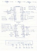
I have drawn the schematic on a piece of paper, I hope its good enough so that intrested people can use it to draw a real schematic and PCB layout.
I wish I had Proteus 6.7 SP3 Professional to draw the scematic, simulate it and draw the PCB, but any owners of proteus would help ??
Enjoy !!
I have drawn the schematic on a piece of paper, I hope its good enough so that intrested people can use it to draw a real schematic and PCB layout.
I wish I had Proteus 6.7 SP3 Professional to draw the scematic, simulate it and draw the PCB, but any owners of proteus would help ??
Enjoy !!
Attachments
Metal, i can very clearly see you are in a whole other leauge than me.
may i ask what educational level you are on? i saw "computer eng." on the schematic, in which case the part on me not understanding squat of that asm file would be clarifyed.
It's still quite some time before i can title myself engineer of any kind.
I will however take some time to think about and study the info and material you have made available to me.
"I'l be back"
Meanwhile, could i reccomend you a litle something to ticle the laughter muscle?
I dont know if your pro or con j.w.bush, but it's fun non the less.
www.jibjab.com
thanks
-Marius
Hi everyone, sorry for late posting, i didn't have much time last week (and will not next 3 weeks 😀 ).
Metal, what can I say, code looks really good, you did a great job! I looked at code quickly and everything seems to be just fine. In a moment i don't have installed PicBasic (good old Windows which crashes every two fu**ing months), so I easily got lost with all variables , and procedures in the notepad. The only thing that i don't like are the controls with tasters, but i think that this is for testing only.
There are two ways to make round, classic, turning knob controls. -First is digital with optocouplers (like in non optical pc mouse) which I made with old potentiometer and parts from pc mouse. It works very good, but only have 30 steps per one revolution. Offcourse, you can buy one but they are expensive and have max. about 50 steps which is quite bad. (but if I recall, TDA chips have about 30 steps?)
-On the other hand, if we go with PIC16F877 chip, we can use A/D input and link to traditional mono potentiometer which will give us plenty of steps, and good old volume knob feeling. 😉 Only problem here is if we make remote control, and if you move volume up or down on remote, the potentiometer stays there. We could use potentiometers with motors, but that's complete waist of money (then we don't need PIC).
Keep posting Metal.
Bye
Mx,
Why not just use a optical/rotary encoder, you could even make one with a pot,
like this one:
http://www.labyrinth.net.au/~steve/opto/
Feels like a pot, and if you usa a remote then you dont need a motor. because its optical!
All we need is someone 2 change some of the code so that we can use a rotary encoder, optical encoder and so on.. and no a push butten, like in the circuit, because i would like to make this circuit but with the optical/rotary encoder!
if someone can do that, meaning chnce the code.. for an encoder of some sort.. it would be great!
Kinser
kinser said:Mx,
Why not just use a optical/rotary encoder, you could even make one with a pot,
like this one:
http://www.labyrinth.net.au/~steve/opto/
Feels like a pot, and if you usa a remote then you dont need a motor. because its optical!
All we need is someone 2 change some of the code so that we can use a rotary encoder, optical encoder and so on.. and no a push butten, like in the circuit, because i would like to make this circuit but with the optical/rotary encoder!
if someone can do that, meaning chnce the code.. for an encoder of some sort.. it would be great!
Kinser
I built exactly the same encoder, that's the first option I was talking about. It works perfectly and the code for it are just two lines in Pic Basic so it isn't problem from programmer point of view, but resolution is small. I have only 30 steps with best mouse encoder I found. You really have to turn knob a lot so the feeling of precise potentiometer is lost, but for some applications it is pretty good solution.
And yes, JibJab is great! 😀
Mx
Hello everybody
I see, regarding the rotary encoder, there are many many types on the market, and most are much expensive than three microswitches. Some of you as I see can make their own rotary switch. Here in jordan, a rotary switch will cost me 15 $.
I think non of you wants the rotary switch to step the volume 30 steps at once, do you, or have the scale degraded by 50steps for the sake of using a rotary switch.
Also there are many ways to deal with rotary switches that I will not mention here, cause my self, I am not going to use any. I have used switches so I can control the circuit by wireless means, rather than just buttons, or rotary encoders, cause pulling the controller's button inputs low serves the job, I mean using another wireless circiuit that can produce low and high outputs only, will be enough.
Also, bear in mind that I have used button command to be able to control the debounce delay and auto repeat speed. If you push the button once, the volume steps half decible, if you hold the button it will start stepping rapidly until you have the level you want.
I had a problem when I first wrote the code that I wanted to mention here, when I hold one of the volume buttons, the reading on the LCD, stays as it is, until I remove my finger, after I remove my finger, the LCD receives the new volume infomation, but this was certainly solved many weeks ago, so even if you hold the one of the volume buttons, the reading on the LCD changes accordingly, and I don't think there are any problems with the code it self.
BTW, Its not necessary to be an engineer to understand what I have done, as some people told me on the email. To be honest, in university, I studdied 8085 microproceesor in one subject only, and used assembly. Four subjects regarding computer architecture, then very huge sujects on networks and networking, that I really dislike, but in future, as I can see from the situations in jordan, the only job available is for networks lovers.
Before that I had dreams of using PICs seriously since I was 18, so I have read lots of books sice the fourth year in university, really lots of books to understand how to program microcontrollers in assembly and PICBasic Pro, I can say I have 2000 pages printed only for PICs, and just bear in mind guys, what I did in PICBasic Pro, can be done using assembly, and these days, I am thinking about quiting PICBasic Pro stuff, and return to assembly.
And last thing to say, being from jordan, doesn't mean I am fond of politics, ok, so all politicians can...
Now, I have finished my part, people we need a PCB design for this project, any volunteers.
Regards
Metal:
I'm certain one does not have to be. My problem is simply that I have just finished my second out of three year electronics-technician education, and so school dont put to much wheight on knowing anything more than the principle of how stuff works. logical enough.
I should stop whining now, and start reading.
Never said Jordanians were, please, I meant no offence.
I just found the site and it's animations fun and somewhat appeling to my anti bush\usa\capitalism line of thought. At least the intent was good.
-Marius
BTW, Its not necessary to be an engineer to understand what I have done
I'm certain one does not have to be. My problem is simply that I have just finished my second out of three year electronics-technician education, and so school dont put to much wheight on knowing anything more than the principle of how stuff works. logical enough.
I should stop whining now, and start reading.
being from jordan, doesn't mean I am fond of politics
Never said Jordanians were, please, I meant no offence.
I just found the site and it's animations fun and somewhat appeling to my anti bush\usa\capitalism line of thought. At least the intent was good.
-Marius
pcb layout
hi guys
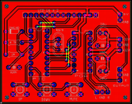
like i promised to Metal, here is the pcb layout of the pga2310. this is not final yet, so comment and inputs are highly appreciated to make the layout better. i made this using my ultiboard 2001.
most of the tracks are about 20mils and for the bigger one are about 40mils.
hi guys
like i promised to Metal, here is the pcb layout of the pga2310. this is not final yet, so comment and inputs are highly appreciated to make the layout better. i made this using my ultiboard 2001.
most of the tracks are about 20mils and for the bigger one are about 40mils.
Attachments
Hello
Really nice work, but you better review the LCD connections, I recommend that you make the connections for the LCD using a connector, looks like the IDE cable connector but not as large. Thats makes your job easier, and more flexible, cuz some one may want to install the LCD on the left, while the PCB is on the right. Also good place for buttons, nice done man 🙂
Also on the right upper corner, where the 5 volt supply input you better add 10uF capacitor, and also on the PIC supply pins, add 1 uF capacitor.
Finally, all I can say, is thanks very much, I really appreciate your help.
When you finish your art work, please upload it as PDF file so I can directly etch mine.
Thanks alot 😉
- Status
- Not open for further replies.
- Home
- Amplifiers
- Chip Amps
- Digitally Controlled Volume, Tone IC ??