Brian,
Any closer to shipping the Darwin??? I almost have my chassis for the Kook done & will begin the amp itself soon. It would be nice just to slide the Darwin right in there with it.
Thx
Mike😉
Any closer to shipping the Darwin??? I almost have my chassis for the Kook done & will begin the amp itself soon. It would be nice just to slide the Darwin right in there with it.
Thx
Mike😉
fieuw just read trough the entire thread 🙂
however i have some questions, as to how it actually operates:
when turned of does it remember the current attenuation/gain, so when turned on again it goes back to that volume?
if i were to create a fully balanced 5.1 preamp and attenuation/ gain controller, i would need one kooka/channel making 6 in total and then you can wire the pots so that there is one master volume control, and the 5 other pot would then be relative to each other
i realy like this idea
or are you willing to reveil some specs of your multichannel preamp that your are designing?
Russ White said:Ok one further thought, but maybe this is way over the line. 🙂 But hey I am having fun.
You run a master pot from one PCB, and run the wiper of that pot to one end of a seperate additional pot on each PCB with the other end of each of those pots being GND. Then you should adjust the level of each PCB individually relative to eachother, but they would all go up and down with the "master" pot.
If you parelleled the output of each PCB you could run 6 PCBs for truly independant 5.1 audio. 🙂
A little far fetched, but it would work!
If you were not interested in left/right adjustments you could actually do it with just 4 PCBs, one for LF/RF one for LS/RS and one parallel for Center and one paralelled for SW.
Maybe I should try to illustrate that....
:EDIT: clarified a bit
It should work as I described it, but honesty I have never tried. When I get a chance I will try it with two kooks plus a master pot. If it works for two it will work for 6.
The 6 channel pre is on hold for the moment, but I may get back to it shortly here. It will be very similar to the kooka.
Cheers!
Russ
The 6 channel pre is on hold for the moment, but I may get back to it shortly here. It will be very similar to the kooka.
Cheers!
Russ
Yes, it remembers the last volume setting.
You would need 3 Kooks for 5.1, each being stereo.
[EDIT]: Oops. Balanced. Yes, 6.
[Edit #2]: And it does not "remember" the volume setting, cause it uses a pot. Having a good day 😉
You would need 3 Kooks for 5.1, each being stereo.
[EDIT]: Oops. Balanced. Yes, 6.
[Edit #2]: And it does not "remember" the volume setting, cause it uses a pot. Having a good day 😉
An idea gone wild
OK folks I was out mowing th lawn when an idea hit me. I think it might have been the gasoline fumes, I am not sure.
Anyway, I thought about the 5.1/7.1 approach for he kooka I had talked about earlier, and wham bang it hit me. Why not make a multi kook volume/PS PCB.
There are two major reasons for doing it:
1) The board can be usd as a seperate PS for the digital section of each Kooka used for the setup. That will lower the noise floor of the kooka even more than it already is.
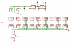
2) It will allow for a "master" volume control with 8 seperate slave volume contols that further adjust each channel.
So for each pot header you would attach a 25K pot. And for the mast volume you would use a 10K pot.
You would then run each of the "kook" headers to its respective kookaburra. The kookas could be run in several combinations, here are a couple:
1) 4 kookas 2 in stereo for front and rear. 1 in mono for center. 1 in mono for sub.
2) 6 kookas each in mono which would allow for left and right balance as well.
Here is the schematic. I have the layout neary done.
Cheers!
Russ
OK folks I was out mowing th lawn when an idea hit me. I think it might have been the gasoline fumes, I am not sure.
Anyway, I thought about the 5.1/7.1 approach for he kooka I had talked about earlier, and wham bang it hit me. Why not make a multi kook volume/PS PCB.
There are two major reasons for doing it:
1) The board can be usd as a seperate PS for the digital section of each Kooka used for the setup. That will lower the noise floor of the kooka even more than it already is.
2) It will allow for a "master" volume control with 8 seperate slave volume contols that further adjust each channel.
So for each pot header you would attach a 25K pot. And for the mast volume you would use a 10K pot.
You would then run each of the "kook" headers to its respective kookaburra. The kookas could be run in several combinations, here are a couple:
1) 4 kookas 2 in stereo for front and rear. 1 in mono for center. 1 in mono for sub.
2) 6 kookas each in mono which would allow for left and right balance as well.
Here is the schematic. I have the layout neary done.
Cheers!
Russ
Attachments
So each kook in my scenario above would have its digital section powered be the preceding circuit, so you would omit R1 nd JG on the PCB which makes the digital section share the +5V analog power supply.
Member
Joined 2002
Re: An idea gone wild
Can i buy some of them fumes 🙂
Russ White said:OK folks I was out mowing th lawn when an idea hit me. I think it might have been the gasoline fumes, I am not sure.
Cheers!
Russ
Can i buy some of them fumes 🙂
Sounds like a great idea 😉
But I have an unrelated question:
Can I add a resister to my 5K pot to give adjustment only to 0dB, ie to cut the last +30dB of adjustment from the pot? if so, what value would I use?
Thanks!
But I have an unrelated question:
Can I add a resister to my 5K pot to give adjustment only to 0dB, ie to cut the last +30dB of adjustment from the pot? if so, what value would I use?
Thanks!
Member
Joined 2003
That could be done and is in fact not that bad of an idea.
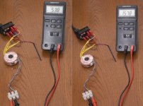
A resistor could be added from 5V to the pot to decrease the controllable voltage. If you know what level 0dB is, then measure the voltage at the wiper of the pot, it is simple ohms law after that to find the required resistor.
Perhaps Russ or Brian know what value should be used, otherwise I will be taking my preamp to school to use an oscilloscope and find out for myself, as I'd like to know for tinkering sake.
Hmm not sure what you are trying to do here let me lay out a fact which may or may not be relevant. The opamp in the PGA2311 is always "on" regardless of the level attenuation/gain. So if you are trying to stay below the "0" point for that reason it will not have any effect.
In any case the very easist way to effect a 0 to -95.5 db range is in the firmware. A resistor could get you there too(or close), but it would depend on the value of the pot you are using.
If you would like firmware for that let me know will work something out.
For a resistor I would try something like a 2-2.7K resistor the positive lead to a 10K pot which should get you close.
Member
Joined 2003
So with the resistor range you suggest we are looking at somewhere between 3.9V and 4.2V into the ADC for a 0dB level. For an absolute 0dB level a measurement must be done.
I am one step ahead of you russ 😉. There is a "firmware" request sitting in your email box. Hopefuly your email hasn't changed since 8 months ago. I won't be able to get around to fiddling with the firmware for a while, but it sure would be nice to have so I can tinker with the Kookaburra. What I might do is change the volume control code a bit to work a little different. For my system the volume control could be a little different. I find myself with the volume knob just under half way for "quiet", and just over half for "loud". So the range I am using is only about 30 degrees of the rotation.
I am one step ahead of you russ 😉. There is a "firmware" request sitting in your email box. Hopefuly your email hasn't changed since 8 months ago. I won't be able to get around to fiddling with the firmware for a while, but it sure would be nice to have so I can tinker with the Kookaburra. What I might do is change the volume control code a bit to work a little different. For my system the volume control could be a little different. I find myself with the volume knob just under half way for "quiet", and just over half for "loud". So the range I am using is only about 30 degrees of the rotation.
wouldnt you loose steps by doing that, either with a resistor or firmware. if you attenuate the output of the first buffer by the right amount with a voltage divider then you will reduce the noise from your input as well as retain all the volume steps.
if you attenuate the output of the first buffer by the right amount with a voltage divider then you will reduce the noise from your input as well as retain all the volume steps.
The buffers are running at 0dB gain. So, you would actually be attenuating the input signal below it's original level, then either attenuating or boosting it at the PGA. I think this would increase noise when in the positive gain portion of the PGA's range (amplifying a smaller input signal).
I think the lost steps are steps they just don't want to use. Of course, another way of doing it would be to simply use a stepped attenuator... 😉
dang that is exactly what I meant head on 
However my limited electronics knowledge wasn't able to think it out myself
I Would really love that pcb, the moment it comes out, I'm emptying my bankaccount for a full blown 5.1 all balanced preamp
Because lets face it there aren't allot of preamps out there with these specs
and while I'm at it I would probally go for motorised pots on the master and subwoofer with IR control, the rest would probally be overkill
my search is over 🙂
thank you
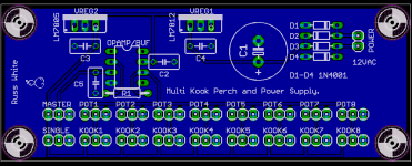
"Perch" layout
Ok so I created a perch on which to nest up to 8 kooks. 🙂Hre is the layout. I will make one and test it with a stero channel and a subwoofer amp. Lets see how she flies. 🙂
Anyway if it works I may be willing to make a couple (self etched) for one or two people if any of you guys are seriously interested in making a go of it.
board size is 1.5" x 4"
Cheers!
Russ
Attachments
- Status
- Not open for further replies.
- Home
- Amplifiers
- Headphone Systems
- Digitally controlled preamp/headphone amp