Digital is NOT analogue, and cannot be viewed or engineered as analogue, digital is very tolerant of system noise and other artefacts that would destroy the analogue information stream. Digital signal understanding, speeds, rise times etc have evolved greatly since a lot of the info from the 1990's, so implementing a relatively slow interface should be well achievable today.
I still hold the view that good engineering of the interface and connectivity would give better results than applying sticking plasters to the problem.
The use of RF attenuators, terminate the digital lines in a weird and wonderful way, a mixture of serial and end termination at both ends, though again the attributes ascribed to these terminators are using analogue views and terminology and effects for digital! The best reference for terminating digital lines (be it end or series termination) is covered in chapter 6 of "high speed digital design" by Howard Johnson & Martin Graham.
Interesting paper on transformers, still used extensivly for digital signal transmission, Ethernet being one of the main examples, others use the Adum isolator devices with silicon transformers, and yesterday I was shown some interesting planar transformers made from folded plexible circuits at a PCB design seminar by Wurth, so the right transformer can be advantageous.
For any that are interested in Signal Integrity, the following links are to the sites of some of today's recognised leading authorities' on the subject. The answers to the digital signal transmission problems will be either covered on the sites or in one of the numerous books, application notes or info these guys have published. Eric Bogatin ran a series of articles titled "No Myths Allowed" which I believe is very apt for digital design and signal transmission... At the end of the day the digital signal will only be 0 or 1.
The sites of the Leading Experts in High Speed Design:
Signal Consulting, Inc. - Dr. Howard Johnson
beTheSignal.com
Welcome
Speeding Edge consultants specialize in high-speed PCB and system design disciplines
The master of EMC (closely related to signal integrity)@
home page
Terminating digital signals:
http://www.pericom.com/pdf/applications/AB023.pdf
http://www.fmsystems-inc.com/manuals/RETURN LOSSart.pdf
http://www.analogzone.com/iot_0919.pdf
Proper Termination for High-Speed Digital I/O Applications - Developer Zone - National Instruments
Proper Termination of High-Speed Digital Signals - Geotest
http://www.altera.com/literature/wp/wp_sgnlntgry.pdf
Digital Signal Transmission
Digital Signal Transmission
Digital Signal Transmission
A free down load:
Right the First Time
A Basic Introduction to Signal Integrity:
Design for Signal Integrity: Unit 1: Introduction to Signal Integrity
Design for Signal Integrity: Unit 02 Integrity of Digital Signals
Just delivered in this months PCD & F (Printed Circuit Design and Fabrication), very relevant to the current discussion.
Printed Circuit Design & Fab Magazine Online
Printed Circuit Design & Fab Magazine Online
Hi Marce
SP/dif > analog or digital it's not an either or, it's both!
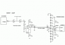
Transmit end is usually from a CMOS digital gate driver with a resistive element including the output driver drain to source Rds on. feeding a transformer. Thevinin sources are used to model drive levels and impedance to matching coax Zo including the transformer turns ratio. Please note the transformers are used to break ground loops and help CM noise suppression in the case of single ended coax SP/dif.
Receive end usually is a 75 ohm termination resistor AC coupled into the clock recovery IC input which consists of a CMOS Schmidt trigger that is a comparator with hysterysis and most times has useful linear gain. here is a good app note that explain Schmidt triggers from Fairchild Inc.
http://www.fairchildsemi.com/an/AN/AN-140.pdf
In my experience it takes more analog expertise to insure so called digital interfaces between systems or seperate PCBs work correctly esp. with independent DC supplies and CM noise. Most CM noise comes from so called "ground bounce" using CMOS devices. http://www.fairchildsemi.com/an/AN/AN-640.pdf
Last edited:
Its digital, its 0s and 1s, and we should use digital engineering and layout techniques, getting the o's and 1's from one end to the other is what we are trying to do.
Again an old application note, look up simultaneous switching noise, again ground bounce, and ground bounce is present on exery digital circuit with switching to as greater or lesser extent. When you have a few FPGA's or processor's on a board you get ground bounce, or Delta I noise, controlling it again is well documented engineering
practice and PCB layout, decoupling schemes etc.
Attachments
Last edited:
The op hasn't been here since the 3rd October!
Marce, I just don't have the time to read all the stuff you linked to (thanks). Can you give us a 2 line summary?
Fran
Marce, I just don't have the time to read all the stuff you linked to (thanks). Can you give us a 2 line summary?
Fran
I cant put all that info into a 2 line summary, same with the books referenced, well maybe I can:
Buy and read the following two books:
Henry Ott, Electromagnetic Compatabilty Engineering.
Howard Johnson/Martin Graham , High Speed Dogital Design.
🙂
Buy and read the following two books:
Henry Ott, Electromagnetic Compatabilty Engineering.
Howard Johnson/Martin Graham , High Speed Dogital Design.
🙂
This article, is a good guide on what not to do (though EMC based, signal integrity is controlling local EMC problems, so it is very relevant).
My favourite are the top two recommendations, considering the fashion for ripping out probably a perfectly adequate clock and adding a 'super clock' hung on the end of some wire!
But the beauty of digital is it is very forgiving, whatever gremlins some Audios will find there (and we haven't even touched on PDS and decoupling)...
The 10 Best Ways to Maximize Emission from Your Product
🙂
Correct orientation?
Two questions from someone on a steep learning curve.
With a 1:1 (4 pin) pulse transformer, is there a correct orientation?
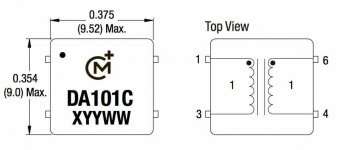
For example, in the Murata DA101C shematic attached, are pins 1 and 2 for signal in while pins 6 and 4 are for signal out? Or does it not matter which side see the signal in?

Am I right in assuming that the dots on on the windings of pins 1 and 6 indicate the active in or out of the respective windings?
Thanks
Two questions from someone on a steep learning curve.
With a 1:1 (4 pin) pulse transformer, is there a correct orientation?
For example, in the Murata DA101C shematic attached, are pins 1 and 2 for signal in while pins 6 and 4 are for signal out? Or does it not matter which side see the signal in?

Am I right in assuming that the dots on on the windings of pins 1 and 6 indicate the active in or out of the respective windings?
Thanks
No, no 'correct' orientation - treat it like any other passive component which isn't polarized. The dots are just there to indicate winding start I think - not related to in or out, just polarity. So if you put a positive going voltage on the dot pin on one side, the dot marked pin on the other side will go positive too.
No, no 'correct' orientation - treat it like any other passive component which isn't polarized.
Thank you.
Joe
Hi,
I just tried the Newava as a replacement for the Murata and I think there is a little more fine detail on percussion. So this has become my favourite now. I'll try comparing this to the Pulse and see how that goes.
cheers
I just tried the Newava as a replacement for the Murata and I think there is a little more fine detail on percussion. So this has become my favourite now. I'll try comparing this to the Pulse and see how that goes.
cheers
- Status
- Not open for further replies.
- Home
- Source & Line
- Digital Source
- Digital pulse transformer : Lundahl, Scientific Conversion, Murata or Newava ???
