Thank panson_hk! My board runs a few days. I made some improvements. TAS5548 is clocked by a separate low jitter oscillator 12.288 MHz. This significantly improves the sound. In power supply circuits have ripple in frequency of several KHz. I installed some additional capacitors Sanyo Oscon 47 and 100 uF. I do not know why, but it affects the quality of the bass and lower middle.
The output filter, I installed two parallel capacitor WIMA FKP2 0.33 uF.
The output filter, I installed two parallel capacitor WIMA FKP2 0.33 uF.
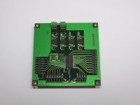
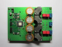
My modulator and power stage modules for multichannel digital amplifier.
I used TAS5548 and TAS5612A (TAS5631B, TAS5614A) chips.
Hi Roman,
Nice work!
Are you selling the modules?
Cheers,
Mike
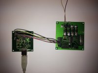
Thanks guys! I have difficulty with the control of the modulator.
I still use Arduino and the test program from the Panson.
I try to write my software, but I have little experience.
I used TPS7A4700 low noise regulators to supply the chips.
In a digital amplifier, there are a few critical things for the sound quality - power supply, clock, inductors, capacitors and digital source.
Please note that the volume control in the TAS5548 provides minimal degradation at the position close to 0 dB. The choice of maximum output power of the amplifier requires accuracy.
Interesting results are obtained by various methods of winding the output inductors.
Hi Roman,
I would like to buy some power stage modules, if you have these for sale.
(I don't need the output inductors or capacitors)
I found this advice from TI: http://www.ti.com/lit/an/slaa605a/slaa605a.pdf
I hope to try this approach but I have little experience also!
Best regards,
Mike
I would like to buy some power stage modules, if you have these for sale.
(I don't need the output inductors or capacitors)
I found this advice from TI: http://www.ti.com/lit/an/slaa605a/slaa605a.pdf
I hope to try this approach but I have little experience also!
Best regards,
Mike
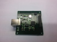
I made the USB interface for control TAS5548/58 internal registers. PurePatch Console defines the module as Audio-EVM 🙂
Cool! What chip do you use?
Did you need to make a custom FW?
Firmware is available for download on the TI website.
- Status
- Not open for further replies.
- Home
- Amplifiers
- Class D
- Digital Amplifier Project