How bad is it really, e.g. on a speaker baffle with sharp 90 degree edges? Let's assume that the response where the listener is located is flat - does diffraction still negatively affect sound quality?
And why does diffraction not seem to affect the Pluto's woofer, even though centered-on-cylinder has one of the most egregious levels of diffraction?
Pluto specs
Is it because the measurement distance is too small? With a woofer that size, somewhere just over 1 kHz the response should show more pronounced peaks and dips... which are not visible.
Just found this Understanding Cabinet Diffraction.pdf - File Shared from Box.net - Free Online File Storage (not read it yet)
Edge diffraction has different properties as the frequency goes down. At high frequencies there is time delayed reradiation transitioning to baffle step loss at low frequencies. What is high or low frequency is a function of edge sharpness (round over) and baffle width. Even at the baffle step around over or champher size affects the ripple in the baffle step transition.

For some real world measures of how big to get how low: "Acoustic Diffraction: Does It Matter?" James Moriyasu (Feb 2003 aXp). Its been a long time since i read it, but what i took away was that the bigger the better and that a champher is almost as effective.
As a 1st hand example, I have both Mar-Ken12t and CGR Mar-Ken12 here. Basically the same box in different formats, the latter with a big champher, and the former with a token champher. It is pretty easy to hear the difference.
dave
Edge diffraction has different properties as the frequency goes down. At high frequencies there is time delayed reradiation transitioning to baffle step loss at low frequencies. What is high or low frequency is a function of edge sharpness (round over) and baffle width. Even at the baffle step around over or champher size affects the ripple in the baffle step transition.
For some real world measures of how big to get how low: "Acoustic Diffraction: Does It Matter?" James Moriyasu (Feb 2003 aXp). Its been a long time since i read it, but what i took away was that the bigger the better and that a champher is almost as effective.
As a 1st hand example, I have both Mar-Ken12t and CGR Mar-Ken12 here. Basically the same box in different formats, the latter with a big champher, and the former with a token champher. It is pretty easy to hear the difference.
dave
I have seen this before - I understand the shape affects the response. But, if the response is then flattened, how does the speaker sound?
What do you mean by flattened? It is not possible to EQ out edge diffraction, one might be a bit more successful with the ripple at the BS but i doubt it.
dave
dave
And why does diffraction not seem to affect the Pluto's woofer, even though centered-on-cylinder has one of the most egregious levels of diffraction?
Is it because the measurement distance is too small? With a woofer that size, somewhere just over 1 kHz the response should show more pronounced peaks and dips... which are not visible.
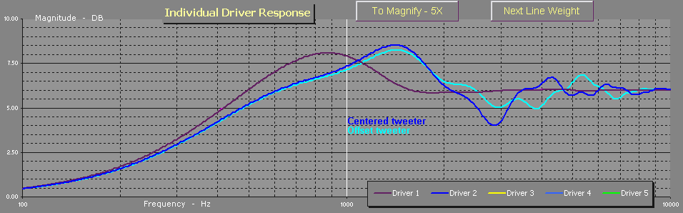
Look at the 3rd response plot from the top.
Pluto electronics
There is your baffle step and diffraction ripple. But that is measured from the top (0°). All this diffraction does not even ocurr at 90° (listener direction), which is not shown here. But that is typical for diffraction. The greatest response changes are mainly on the main sound propagation axis.
As a result, the listener is only exposed to it in vertical direction where we are less sensitive and the baffle step peak is even already in the stop band (>1KHz) where the response is down > 10dB.
Here is another good read.
Frequently Asked Questions
Last edited:
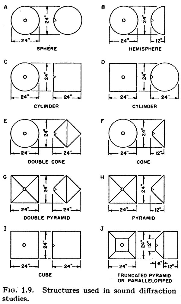
Olson's Work
The figures shown here come from [1] and the paper [2] by the same author.
Regards,
WHG
[1] Acoustical Engineering,” Harry F. Olson, D. Van Nostrand Co., Inc., 250 4th Street, New York 3, NY 1957
BKPA1 - Acoustical Engineering
[2] Direct Radiator Loudspeaker Enclosures
Even though a direct radiator loudspeaker mechanism produces a uniform acoustical output with respect to frequency the diffraction effects of the enclosure may introduce wide variations in the frequency response. To determine the diffraction effects, a small direct rdiator loudspeaker mechanism was designed and constructed to deliver uniform sound output with respect to frequency. This loudspeaker mechanism was mounted in twelve enclosures of different shapes and the frequency response characteristic was determined experimentally. The experimental results agree with the theoretically predicted performance in the cases where the performance can be determined by theoretical considerations. A cabinet has been developed which exhibits a smooth frequency response characteristic and still retains an exterior which is acceptable from the standpoint of appearance.
Author:Olson, Harry F.
Affiliation:RCA Laboratories, Princeton, NJ
JAES Volume 17 Issue 1 pp. 22-29; January 196
AES E-Library Direct Radiator Loudspeaker Enclosures
And why does diffraction not seem to affect the Pluto's woofer, even though centered-on-cylinder has one of the most egregious levels of diffraction?
Pluto specs
Is it because the measurement distance is too small? With a woofer that size, somewhere just over 1 kHz the response should show more pronounced peaks and dips... which are not visible.
Hi,
Its because to see it in action requires a small source compared to the
baffle, such that path lengths to the edges are quite similar and reinforce.
(Why the Olson studies are as symmetrical as possible, with a small source.)
(Why you offset midranges and treble units, to vary the path lengths.)
A large pistonic source on a similar sized baffle has very varied path lengths
which smooths the effect leaving the 6dB baffle step effect + usually a mild
hump of around 2dB above that before settling to +6dB.
rgds, sreten.
Last edited:
I was under the impression that baffle edge diffraction and baffle step compensation are two different problems with different solutions.
Baffle edge diffraction can largely be fixed by rounding over the edges. It affects tweeters.
http://www.silcom.com/~aludwig/images/diffdem.gif
Baffle step compensation affects bass or low mids because the speaker goes from full space to half space radiation.
Can be fixed in the xover or by soffit mounting the speakers.
One note, often missed, on roundovers-
They're useful even when they're smaller than ideal. The reason is, trace the rays- the further from 90 degrees the angle of incidence to the baffle, the longer a given roundover/bevel takes to complete. a 1" roundover could look like 3" if it's the portion on the bottom of a floorstanding 6.5" "average" tower (bottom being far from the midwoof)
They're useful even when they're smaller than ideal. The reason is, trace the rays- the further from 90 degrees the angle of incidence to the baffle, the longer a given roundover/bevel takes to complete. a 1" roundover could look like 3" if it's the portion on the bottom of a floorstanding 6.5" "average" tower (bottom being far from the midwoof)
The figures shown here come from [1] and the paper [2] by the same author.
Don't know about the paper [2] but the images i posted were scanned from pages 22 & 23 of one of my copies of Acoutical Engineering.
dave
I was under the impression that baffle edge diffraction and baffle step compensation are two different problems with different solutions.
They are the same phenomenom, but with side effects that transition from one state to another as a function of frequency. It is common to call the HF state as diffraction, and the LF state as baffle step, but in the middle it is a mixture.
to illustrate this, the full term for baffle step is baffle step diffration.
dave
Interesting. I didn't know that. This phenomenon exists even when the driver is behaving pistonically, I assume?Hi,
A large pistonic source on a similar sized baffle has very varied path lengths
which smooths the effect leaving the 6dB baffle step effect + usually a mild
hump of around 2dB above that before settling to +6dB.
rgds, sreten.
Interesting. I didn't know that. This phenomenon exists even when the driver is behaving pistonically, I assume?
Hi,
an example : http://zaphaudio.com/SR71.html

Bass unit with tweeter in central and offset positions :
I assume the modelling assumes pistonic for the bass / mid unit.
rgds, sreten.
Last edited:
They are the same phenomenom, but with side effects that transition from one state to another as a function of frequency. It is common to call the HF state as diffraction, and the LF state as baffle step, but in the middle it is a mixture.
to illustrate this, the full term for baffle step is baffle step diffration.
dave
Could you run that past me please because looking at it it would seem the two have different causes, caused by different phenomena with different solutions (except soffit mounting of the speaker).
For starters baffle edge diffraction appears to be largely unrelated to baffle width and results in phantom treble sources at the edge (and possible comb filtering) while uncompensated baffle steps result in a lack of bass in free standing speakers only.
(My own speakers use conical 90deg horns for treble, as most Tannoy DCs do, and are positioned with their backs on the wall hence I did not address either problem and the speakers are +-2dB at the listening position at 1/3 oct resolution.)
Could you run that past me please because looking at it it would seem the two have different causes, caused by different phenomena with different solutions (except soffit mounting of the speaker).
All of the programs that I am aware of that model diffraction are based on ray-tracing, and they use one mathematical model that predicts both the baffle step and the dips and peaks from diffraction for shorter wavelengths.
The first publicly available program that modeled diffraction for loudspeakers was written by Paul Verdone and it is available on the FRD Consortium site. The Operations Manual has extensive discussion of the theory and even includes the Excel equations for most calculations: http://www.pvconsultants.com/audio/diffraction/downloads/opmanrel6.07.exe Read that and you will have a better understanding of the underlying theory.
I implemented the same approach in a .NET version of program that you can download at the following URL. My program is in a beta state with the feature set fixed, lots of code that works and some code that needs to be finished. The baffle diffraction part of the program is still undergoing significant revision. However, the posted code accurately calculates diffraction for simple shapes, and it allows you to quickly see the effect of driver location and baffle dimensions. (you can drag the drivers around or drag the cabinet edges).
The program also uses some CompactSQL databases, and it takes a while to install all of the the database components. However, once the clients are available on your computer, the program installs and updates quickly. It's all standard Microsoft stuff that gets installed -- it is "safe".
http://www.audiodevelopers.com/Software/PSD.zip
As planet10 says, it's different manifestations of the same phenomena, and it can be hard to visualise conceptually.Could you run that past me please because looking at it it would seem the two have different causes, caused by different phenomena with different solutions (except soffit mounting of the speaker).
For starters baffle edge diffraction appears to be largely unrelated to baffle width and results in phantom treble sources at the edge (and possible comb filtering) while uncompensated baffle steps result in a lack of bass in free standing speakers only.
Try this description by Linkwitz to see if it helps, as he describes it in terms of a time domain phenomena, which is what it really is:
Frequently Asked Questions
One comment I would make about baffle diffraction (ripples) is that it's generally a lot less of a problem with most drivers than most simulations show.
The overall 6dB step you can pretty much count on occurring (unless the driver is large and starts to become directional very close to the baffle step frequency, in which case a full 6dB wont get a chance to manifest) and the first overshoot and dip predicted usually occurs, but beyond that what a simulator predicts and what happens in reality starts to diverge significantly.
This is partly because most simulators are 2D approximations, not full 3D simulations. This introduces two sources of error - in some simulators the "edge" is assumed to be a 90 degree angle, but this is not always the case, and the amplitude of the re-radiated diffraction signal is dependant on how sharply the wave has to bend - the sharper it bends, the greater the amplitude.
The most obvious example is comparing a standard shoebox shaped cabinet with an equivalent size open baffle - in the normal cabinet the wave diffracts 90 degrees then has to travel the full depth of the box before diffracting again, whereas with an open baffle (without wings) the wave is diffracting 180 degrees around the edge of the baffle - so any baffle step ripples in response will be far greater in magnitude with a plain open baffle than a box, and the box depth does have some effect on the result - something that most simulators ignore.
(A true open baffle would also have the rear wave diffracting around to the front as well, but the increased diffraction I describe would still happen on an open baffle with a sealed back driver such as a tweeter)
Another source of error is improper modelling of the directivity of a driver. Most diffraction models seem to use a flat piston model for drivers, approximating the cone area by using a large number of point sources within a flat circle. This doesn't do a very good job of modelling the response of a cone shaped driver, and over-estimates how much signal travels along the baffle towards the edge at high frequencies.
A real driver, especially a cone driver of significant size, is a lot more directional than the simplistic modelling assumes, which means that most of the nasty looking response ripples beyond the first overshoot peak and undershoot dip typically don't actually manifest. The more directional the driver is the less ripple. Beyond the frequency where the drivers natural directivity is significantly less than 180 degrees, baffle diffraction ripples go away, as the baffle is not illuminated.
Another example is any kind of tweeter with a waveguide, (ribbon, horn etc) which constrains the radiation at the mouth to much less than 180 degrees - there is so little radiation at right angles to the front plate that very little if any cabinet edge diffraction occurs. (I would still flush mount the driver though) On the other hand cabinet edge diffraction from a typical dome tweeter with a protruding dome really does matter a lot.
The way I view baffle diffraction simulators is that they can show you at which frequencies peaks and dips are likely to occur for a given baffle shape and driver location, but not the true amplitude of the ripples, or whether higher frequency ripples will even manifest or not - for this you must rely on measurements.
A 90 degree horn which maintains its pattern over it's entire working range won't have any problems with baffle diffraction from the cabinet edge. The only diffraction issues it will have are any built in ones - for example if the inner edge of the mouth doesn't have a smooth radius to the flange, but that's a design problem with the horn in that case.(My own speakers use conical 90deg horns for treble, as most Tannoy DCs do, and are positioned with their backs on the wall hence I did not address either problem and the speakers are +-2dB at the listening position at 1/3 oct resolution.)
Last edited:
...This is partly because most simulators are 2D approximations, not full 3D simulations...
I know of 4 widely available diffraction simulators: Paul V's BDS Excel program, Jeff Bagby's Baffle Diffraction and Boundary Simulator, The Edge from Tolvan Data, and my program. All of them are full 3D simulations, where the phase and amplitudes of the rays from the source and reflections are summed at a point in 3D space. My program does over 8 million ray summations for a typical 8" driver--it is a lot of processing. 3 of the programs in this list use some sort of approximation to calculate the effect of roundovers on the baffle edges, and 3 of these programs can accurately predict the effect of the backwave interacting with the sources on the front for a dipole configuration. So your account of the limitations of these models isn't accurate.
There are a number of ways in which the models can be improved, but Jeff Bagby did a lot of comparisons of his model with actual measurements and found that his model is already fairly accurate. One possible improvement is factoring in the effect of re-radiation from the edges. That is, the reflected waves can be viewed as sources which have their own diffraction signatures. None of these models currently address this, and it there is some published work that suggests this effect might be significant. Another improvement is factoring in the 1/N^2 losses due to different lengths of the rays. I added this factor to my model, and it results in a somewhat less than 6db overall baffle step and a somewhat less pronounced peak at the step frequency. I believe that this model is more accurate, particularly for predicting the response at close distances (summation point less than 4 feet, for example).
Neil,
How would your program model something like the TPL-150 ribbon driver?
The driving element is not a circular source. Will it do the calculation.
I am curious on your opinion of how well LEAP5 might model diffraction or are these programs you mentioned in a different league?
Neil,
How would your program model something like the TPL-150 ribbon driver?
Right now I don't have a source model for rectangular drivers. Maybe later--I have provisions in the data model for either circular or rectangular dimensions, and it isn't any harder to do rectangular drivers, but I haven't implemented that yet. I know The Edge does rectangular dirvers, and some of the other programs might also.
The entire enclosure modeling part of my program was actually a diversion from the real goal, which is to simplify the design of crossovers for active speakers. The code in the link is actually a passive crossover version of the program, which is even more of a diversion 🙁. It might be a while before I implement a rectangular driver model--I've got too many other challenges in the queue.
I am curious on your opinion of how well LEAP5 might model diffraction or are these programs you mentioned in a different league?
I had never looked at the LEAP5 program before today. From the description it looks impressive. There is nothing really too hard about the diffraction modeling (it's really just lots of geometry calculations), so I assume that their model is as good as the others.
To be honest with you, all of those little ripples in the response due to diffraction may look bad on paper, but in the real world they don't amount to a whole lot. They show the summation at a single point in 3D space, but if you move from that point just slightly the solution can be quite different. You don't want to optimize a crossover response for a single point in space, so it isn't clear what to do with all of that information. The diffraction effect that is most important is the baffle-step region. I had actually contemplated using a simpler model that just predicted the baffle step region. But even modeling this region of the response isn't as simple as you might expect, because for an accurate model you need to consider floor-bounce, wall reflections, room damping, etc...
Last edited:
Right now I don't have a source model for rectangular drivers. Maybe later--I have provisions in the data model for either circular or rectangular dimensions, and it isn't any harder to do rectangular drivers, but I haven't implemented that yet. I know The Edge does rectangular dirvers, and some of the other programs might also.
The entire enclosure modeling part of my program was actually a diversion from the real goal, which is to simplify the design of crossovers for active speakers. The code in the link is actually a passive crossover version of the program, which is even more of a diversion 🙁. It might be a while before I implement a rectangular driver model--I've got too many other challenges in the queue.
I had never looked at the LEAP5 program before today. From the description it looks impressive. There is nothing really too hard about the diffraction modeling (it's really just lots of geometry calculations), so I assume that their model is as good as the others.
To be honest with you, all of those little ripples in the response due to diffraction may look bad on paper, but in the real world they don't amount to a whole lot. They show the summation at a single point in 3D space, but if you move from that point just slightly the solution can be quite different. You don't want to optimize a crossover response for a single point in space, so it isn't clear what to do with all of that information. The diffraction effect that is most important is the baffle-step region. I had actually contemplated using a simpler model that just predicted the baffle step region. Of course even this response isn't as simple as the models predict, because you need to consider floor-bounce, wall reflections, room damping, etc...
Thanks, Neil.
To be honest I had not put much effort into diffraction at this point for the reason you have mentioned. There are so many things going on in the room that compound the whole thing.
The biggest hurdle I have found is getting measurements that you can hang your hat on. It is difficult with a large speaker in a mid-sized room with a ceramic tile floor. ;-)
- Status
- Not open for further replies.
- Home
- Loudspeakers
- Multi-Way
- Diffraction