On the Curve Sided Loudspeaker page posted a short time ago, the transverse lamination examples have flat baffles...
I want to incorporate this lamination method into my design but was wandering why the enclosures shown have stopped short of going for a full rounded baffle - which would have helped further reduce diffraction effects. Or is this incorrect?
I want to incorporate this lamination method into my design but was wandering why the enclosures shown have stopped short of going for a full rounded baffle - which would have helped further reduce diffraction effects. Or is this incorrect?
Vikash said:I want to incorporate this lamination method into my design but was wandering why the enclosures shown have stopped short of going for a full rounded baffle - which would have helped further reduce diffraction effects. Or is this incorrect?
Personally, I went as far as I could with the rounding. Just couldn't get round the fact that you need a flat surface to mount the drive-units to.
Other than that, you have to juggle height, depth, width and wall thickness to end up with the right volume.
Good luck with your Translams, Vikash. Post us any drawings or photos when you have them.
Steve
Hello Steve,
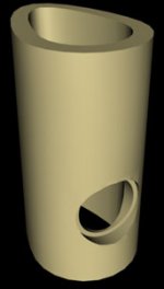
Just thought i'd bounce an idea of you...
The driver would only be flush on part of the baffle. Don't know if i'm gaining something or losing something. Certainly looks cool 🙂
...need a flat surface to mount the drive-units
Just thought i'd bounce an idea of you...
The driver would only be flush on part of the baffle. Don't know if i'm gaining something or losing something. Certainly looks cool 🙂
Attachments

Still awake and on the forum like a true fanatic i see 🙂
It's egg all the way! Outside for diffraction, inside for standing waves.
It's egg all the way! Outside for diffraction, inside for standing waves.
I've decided on the Seas W22EX002. Tweeter yet to be decided. Choices are reduced due to the low cut off required for the mid range. And it doesn't help that I have no crossover designing experience. Well, one thing at a time.
It's as much about the journey as the ending right...
It's as much about the journey as the ending right...
The downside of course are the sharp edges in front of the driver.
I guess I would have a short cylinder extending out to the frontmost edge of the curved baffle so the top and bottom of the cylinder would extend the same as the baffle but the sides would be a couple of inches long. Then mount the driver in the end of the cylinder. Inside and outside eggs seem the way to go....
I guess I would have a short cylinder extending out to the frontmost edge of the curved baffle so the top and bottom of the cylinder would extend the same as the baffle but the sides would be a couple of inches long. Then mount the driver in the end of the cylinder. Inside and outside eggs seem the way to go....
Heavily chamfer the front edges to the driver? Do that, and you won't have egg all over your face.
correct me if I'm wrong, but the sharp edges in front of the driver won't be *much* of a problem if the driver is crossed over fairly low...
though, if you're going for full-range, maybe that's not an option.
*shrug*
though, if you're going for full-range, maybe that's not an option.
*shrug*
EC8010 said:Heavily chamfer
Attachments
Member
Joined 2002
the sharp edges in front of the driver won't be *much* of a problem if the driver is crossed over fairly low
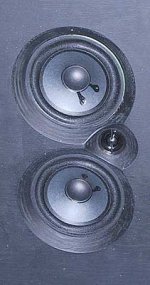
It will be a problem overall in that case. I mean the tweeter will be mounted in a similar cutout.
The enclosure image was a bit exaggerated. The amount of curve would probably be kept to a minimum as it approaches the centre of the drivers, and so the edges won't be as pronounced.
I like the idea of chamfering. (Thanks for the image to pre-empt me asking what that is 😉) That might work well with the same exaggerated curve. Chamfering seems to be doing the same thing for diffraction but carved in the opposite direction. Any comments?
Attachments
Bricolo,
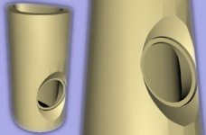
I was wondering the very same thing. It seems to me from the
picture that Dave posted that on the midrange you would gain
some horn loading effect and on the tweeter the off axis response
would be a bit different across the horizontal plane.
The question is how much effect would this have on the sound?
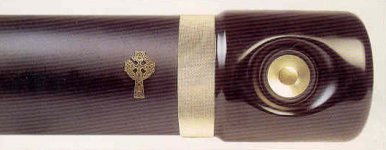
It's been done before
That's good. Provides some reassurance. I hope those speakers are expensive!
The question is how much effect would this have on the sound
I've just downloaded the diffraction simulator. Although I'm not sure if I'll be able to model an enclosure like this.
Looks good. It's been done before, mind. The loudspeaker is the Celtic Audio "Caber".
There are some good words about the £5500 Caber on their site (but off course):
...there is no disturbing diffraction from the enclosure...
looks like a promising idea.
currently working on.....
a 6ft tall cone, (really a tapered quartewave pipe), the driver for this will be on a flat piece level with the surface at top and bottom and rounded neatly over to meet the cone as a smooth join , I hope !
(well actually, its now about 4' tall, and i keep thinking maybe I ought to get on with the rest of it one day 😉
- Status
- Not open for further replies.
- Home
- Loudspeakers
- Multi-Way
- Diffraction/Rounded Baffle