Hey all, haven't been here for a while, nice to be back. I'm planning to build a pair of Marantz Model 9 amps this winter and I have a question. I'm awaiting the arrival of a pair of Sowter input transformers, 10k/10k. I bought them because the English economy is on the skids and the price was very good. I would start by fixing the low frequency filter. And also do away with the phase inverter and the first half of the 6DJ8. But my real question is about conversion to a differential amplifier with a transformer input. Would it compromise the quality of the amp? Or is it build it and see thing?
Last edited:
For the last question, you can make a differential amplifier joining the cathodes toguether and to ground via a resistor or CCS. Both grids with leak to ground and the secondary of transformer directly to borh grids. Plate circuits, as you need.
No necessary to build a LTP. prhaps once an image is better than tons of words. If the trafo has a center tap, use only a resistor of proper value to load it. Else use two seriers resistances half value and the joint earthed to give grid leak. Plate circuit as you need.
Attachments
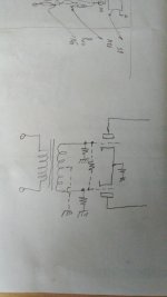
The 3575 has the center tap and it is 1=1 ct 10k=10 bridging
So the secondary has a center tap.
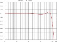
It is a very good stuff but take care on frequency answer with a proper Zsource.
It will possible to add a Zobel network on each raw of the secondary in parallle ot he desidered value that I see as 10k-22k
In attach one of my old measure of 3575
So the secondary has a center tap.
It is a very good stuff but take care on frequency answer with a proper Zsource.
It will possible to add a Zobel network on each raw of the secondary in parallle ot he desidered value that I see as 10k-22k
In attach one of my old measure of 3575
Attachments
Above is a copy of a modified Model 9 schematic. I don't remember where I found it but it might be a good starting point as it uses your recommendations for a CCS between the cathodes of the first pair of tubes. Waltube, is the Zoebel network there to rolloff the signal to avoid very high frequency oscillations?
That new Marantz 9 diagram cannot work. The 6CG7 cathodes are connected together and not providing a differential signal to the EL34s.

Rayma, I concede your point. I could build an exact clone like I did in the past for a Model 8 using ST70 output transformers. It sounded wonderful. The unity first 6DJ8 is unnecessary as I won't need the phase shift option. And the adjustable damping is unnecessary as well because I won't be using the amp for bass reproduction. That said I won't have actual Marantz transformers. Years ago I had a long phone conversation with Doc Hoyer who gave me all the necessary information to have the outputs recreated. In the early sixties he rebuilt a model 9 output that had been in a flood. So yes it won't be a Model 9 but it will still be a great amplifier if I get it right. I've built four amplifiers using Pete Millet's uniamp circuit one with some very expensive AD1 output tubes and they all sounded great. And that was using inexpensive Edcor 10k/10k input transformers. The sound of the model 8 & 9 is dominated but the EL34, I love that midrange. So I'm sure I'll be happy with the result.
Yea HollowState that's pretty obvious. Must have been one of my lame attempts. But the original circuit will work as it is, correct, except for the input? Do you know if valve 1b provides any gain? It seems to be the primary voltage amp. And can you tell me what is NE 2v is?
Last edited:
"Do you know if valve 1b provides any gain?" "And can you tell me what is NE 2v is?"
In your "new" Marantz 9 it does not. In the original yes it does. And an NE2 is a small neon bulb placed there to limit grid to cathode voltage during start up protecting the 6DJ8 tube.
In your "new" Marantz 9 it does not. In the original yes it does. And an NE2 is a small neon bulb placed there to limit grid to cathode voltage during start up protecting the 6DJ8 tube.
Attachments

Last edited:
Since the 6DJ8 is no longer in production there isn't any reason I could substitute 6922 is there?
Hi waltube if I understand your post I would need to add an RC network from the secondary end taps of the 3575 to the center tap which is attached to ground. And if that is the case could the 47k grid resistor be paired with a 150pf cap for a cutoff of around 22k? Or would the RC need to be separate from the grid resistor?
Hi waltube if I understand your post I would need to add an RC network from the secondary end taps of the 3575 to the center tap which is attached to ground. And if that is the case could the 47k grid resistor be paired with a 150pf cap for a cutoff of around 22k? Or would the RC need to be separate from the grid resistor?
Member
Joined 2009
Paid Member
Yes, equivalent current production tube should be fine
https://www.jj-electronic.com/en/e88cc-6922-6dj8
https://www.jj-electronic.com/en/e88cc-6922-6dj8
On second thought grid leak is DC so they have to be separate.Since the 6DJ8 is no longer in production there isn't any reason I could substitute 6922 is there?
Hi waltube if I understand your post I would need to add an RC network from the secondary end taps of the 3575 to the center tap which is attached to ground. And if that is the case could the 47k grid resistor be paired with a 150pf cap for a cutoff of around 22k? Or would the RC need to be separate from the grid resistor?
Is that because the 6CG7 are driving EL34's from the cathodes? If I give each 6CG7 it's own cathode resistor would that work? And do they share a cathode resistor to help balance the pair?That new Marantz 9 diagram cannot work. The 6CG7 cathodes are connected together and not providing a differential signal to the EL34s.
Eureka! I found four 6DJ8's in with the eight winged C's I bought for this amp years ago. I can always replace them later with 6922'sYes, equivalent current production tube should be fine
https://www.jj-electronic.com/en/e88cc-6922-6dj8
- Home
- Amplifiers
- Tubes / Valves
- Differential 9 Power Amplifier